- Physics Lab Equipment
- Chemistry Lab Equipment
- Biology Lab Equipment
- Anatomical Lab Equipment
- Learning
- Educational Lab Equipment
- Magnets
- Agriculture
- Astronomy
- Earth Science
- Geography Lab Equipment
- Safety Lab Coat
- Laboratory
- Meteorological
- Electricity & Magnetism
- Heat
- School Lab Equipment
- Lab Glassware
- Science Lab Equipment
- Tvet Lab Equipment
- Robotics Kits Supplier and Manufacturer for Schools India
- Math Lab Equipment Manufacturers and Exporters in Ambala
- STEM Kits Manufacturers and Supplier India
- Engineering Lab Equipment
- Hospital Lab Equipment
- Water, Sanitation & Hygiene Supplies
- Cold Chain, Solar & Communication Equipment
- Nutrition
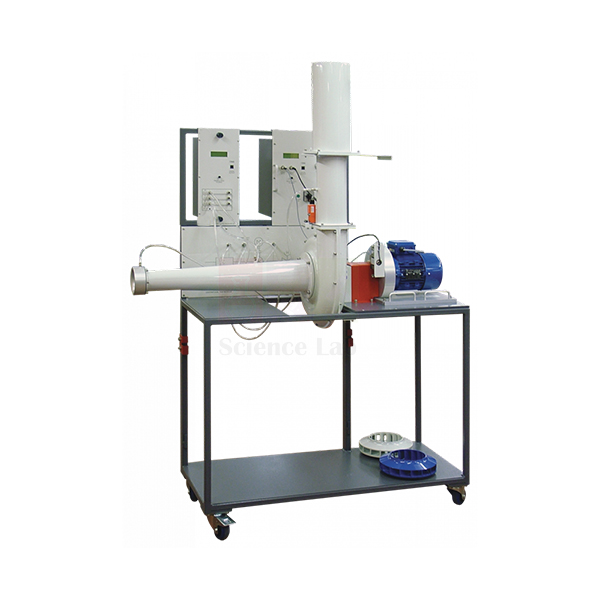
Centrifugal Fan Module
Centrifugal Fan Module (Product Code: SLE/EFM/15) is a trolley-mounted test rig for measuring how a centrifugal fan performs as its speed and airflow change. The module carries the fan and its instrumentation on a robust, mobile trolley, and it comes with three different impellers so students can compare blade designs on the same housing. It is designed for mechanical engineering turbomachinery and air-handling practicals, and is made by Jain Scientific Equipments Pvt Ltd (ScienceLab), Ambala, a technical educational equipment manufacturer.
Specifications
| Parameter | Detail |
|---|---|
| Layout | Fan and instrumentation mounted on a robust, mobile trolley |
| Impellers | Interchangeable; three different impellers supplied with the fan |
| Speed | Fully variable up to the maximum allowable for the fan |
| Speed, torque and power | Measured by the Universal Dynamometer |
| Airflow measurement | Shaped inlet nozzle used to measure the airflow rate |
| Airflow control | Slide-valve; air discharges past the valve to atmosphere |
| Safety | Housing interlock — the motor cannot run unless the fan is assembled correctly |
Typical Use
A standard practical holds the fan at a fixed speed and closes the slide-valve in stages, recording the pressure difference across the shaped inlet nozzle (which gives the airflow rate) together with the speed, torque and absorbed power from the Universal Dynamometer. From these readings students plot pressure rise, power and efficiency against flow, producing the fan characteristic curves covered in fluid machinery courses. Repeating the test at other speeds lets them check the fan laws, and swapping to each of the three impellers shows how blade shape changes the curves.
The interlocked housing means an impeller change can be done safely: switch off, open the housing, fit the next impeller and close it again before the motor will restart. Keep the inlet nozzle free of dust and obstructions, since its reading sets the flow for every result. Wheeling the trolley between labs makes one module practical for several batches of students.
Manufacturer
Engineering teaching rigs such as this fan module are built by Jain Scientific Equipments Private Limited, which operates as ScienceLab from Ambala in Haryana, India. You can read about our history and capabilities on the company profile.
Related Fluid Mechanics Equipment
Equipment that works with, or alongside, the fan module in a turbomachinery lab:
- Universal Dynamometer — measures the speed, torque and power absorbed by the fan
- Pipe Flow And Nozzle Kit — pipes that connect to a fan inlet for suction-flow tests; ask us to confirm pairing
- Axial Flow Pump Module — compares a different rotodynamic machine in the same course
- Reciprocating Compressor — contrasts a positive-displacement air machine with the fan
For pumps, turbines and more, open the Fluid Mechanics category.
Frequently Asked Questions
How many impellers are supplied?
Three different impellers are supplied with the fan, and they are interchangeable in the same housing.
Is the Universal Dynamometer part of this module?
The dynamometer provides the speed, torque and power readings and is also listed as a separate product. Please confirm in your enquiry whether you need it supplied with the module.
How is airflow measured and controlled?
Air enters through a shaped nozzle used to measure the airflow rate, and a slide-valve downstream sets how much air flows before it leaves to atmosphere.
Can students change the impeller safely?
Yes. An interlock on the fan housing stops the motor from running unless the fan is correctly assembled.
What is the maximum fan speed and power supply?
Speed is fully variable up to the fan’s maximum allowable value; the figures and mains requirement are not in our current listing, so please contact us.
Is a calibration certificate available for the instrumentation?
Talk to us about certificate needs when you request a quote; availability depends on the order.
What does an institutional quotation require?
Tell us the quantity, whether the dynamometer is needed, your delivery address and any tender format, and we will prepare the offer.
Request a Quote
For pricing on the Centrifugal Fan Module, get in touch or add it to our enquiry cart. We deliver to institutions in India and international markets.
Last updated: 24 September 2026
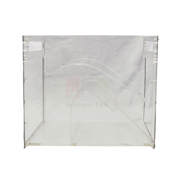
Self Regulating Siphon
Self Regulating Siphon (Product Code: SLE/EFM/16) is a clear acrylic hydraulic model that shows a siphon adjusting its own discharge over a wide range while holding the upstream water level almost constant. Unlike a simple siphon that runs either full or not at all, this one passes a mixture of air and water, which is the key to its self-regulating behaviour. The model helps civil and water-resources engineering students understand siphon spillways used for level control, and it is made by Jain Scientific Equipments Pvt Ltd (ScienceLab), Ambala, as part of its vocational training and engineering lab equipment.
Key Details
| Parameter | Detail |
|---|---|
| Type | Self-regulating siphon model |
| Material | Clear acrylic |
| Function | Adjusts its discharge automatically over a wide range |
| Upstream level | Kept mostly constant as discharge changes |
| Flow through siphon | Mixture of air and water |
| Suitable for | Open-channel hydraulics teaching and demonstration |
Typical Use
In a demonstration, the inflow to the model is raised in steps while students watch the siphon barrel through the transparent walls. At modest flows the siphon draws in air along with the water; as inflow increases, less air enters and more water passes, so the discharge rises while the upstream level barely moves. Recording the upstream level against discharge produces a remarkably flat curve, which students then compare with the steep level–discharge relationship of an ordinary weir or gate.
The model links neatly to real practice in canal and reservoir design, where siphon spillways protect structures from over-topping without moving parts. Fit it level and watertight in your channel, change flow slowly so each condition can settle, and rinse the acrylic with clean water after use. The mounting arrangement depends on your channel, so confirm fitting details with us before ordering.
Manufacturer
ScienceLab is the product brand of Jain Scientific Equipments Private Limited, an Ambala, Haryana company that builds hydraulics models for technical education. For tender and vendor registration, our details are GSTIN 06AAECJ8618A1ZT and LEI 3358004HRD1JIVXKYX49. The company profile page gives a fuller picture of the business.
Related Fluid Mechanics Equipment
Channel models used in the same series of open-channel experiments:
- Meter Flume — a recirculating laboratory flume to host channel models; confirm fitting with us
- Sluice Gate with Tappings — a gated control structure to contrast with siphon regulation
- Energy Dissipation — studies what happens to high-energy flow below spillway structures
- Culvert — another clear model showing how flow type changes with water level
Explore the wider Fluid Mechanics range.
Frequently Asked Questions
What makes this siphon “self-regulating”?
It passes a mixture of air and water, so its discharge adjusts automatically over a wide range while the upstream water level stays mostly constant.
Can students see what happens inside?
Yes. The model is clear acrylic, so the air–water mixture in the siphon is visible throughout the test.
Does it include a water supply or channel?
No supply or channel is listed with the model. Send us details of your flume or channel through the contact page and we will advise on fitting.
What size is the model?
Dimensions are not given in our current product details; ask us for a drawing before ordering.
How should the acrylic be cleaned?
Use clean water and a soft cloth; avoid solvents and abrasive cleaners, which can scratch or craze the surface.
Can you supply it for tenders or overseas orders?
Yes. We quote for institutional tenders and ship to India and international markets; include your quantity and destination.
Request a Quote
To price the Self Regulating Siphon, contact us or add it to your enquiry cart along with any other channel models you need.
Last updated: 24 September 2026
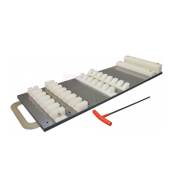
Energy Dissipation
Energy Dissipation (Product Code: SLE/EFM/17) is an open-channel accessory for studying how the energy of fast-moving water is dissipated below a hydraulic structure. It consists of a long apron and a selection of toothed and solid blocks that can be arranged in any combination on the apron, and it is designed to be used with the Spillway with Tappings. Civil and irrigation engineering departments use it to teach stilling-basin design, and it is manufactured by Jain Scientific Equipments Pvt Ltd (ScienceLab), Ambala, a TVET and engineering lab equipment manufacturer in India.
Key Details
| Parameter | Detail |
|---|---|
| Main component | Long apron |
| Blocks | Selection of toothed and solid blocks |
| Arrangement | Blocks can be placed in any combination on the apron |
| Used with | Spillway with Tappings (not part of this item) |
| Purpose | Study of the dissipation of energy |
Typical Use
Water leaving a spillway is fast and shallow, carrying enough energy to scour a riverbed if it is not tamed. With the apron placed downstream of the spillway, students first observe the flow and the hydraulic jump on the plain apron, then add toothed and solid blocks in different layouts and watch how the jump shortens, stabilises or moves. Measuring the water depths before and after the jump lets them calculate the energy lost for each arrangement and judge which layout performs best as a stilling basin.
Because the blocks can be arranged freely, groups can be set design challenges — for example, reaching a stable jump within the shortest length of apron. Record every layout with a sketch or photograph so results can be compared later, and dry the blocks before storage. The set is equally suited to TVET lab equipment lists for water-engineering diplomas and to degree-level hydraulics courses.
Manufacturer
The apron and block set is manufactured by Jain Scientific Equipments Private Limited, which trades as ScienceLab and operates from Ambala, Haryana. More about our work with engineering institutions is on the company profile page.
Related Fluid Mechanics Equipment
Channel equipment that fits the same spillway and scour experiments:
- Meter Flume — a recirculating flume to run the spillway and apron in; confirm fitting with us
- Sluice Gate with Tappings — another way to create fast flow ahead of a hydraulic jump
- Bridge Piers — continues the topic with scour of the stream bed around piers
- Self Regulating Siphon — an alternative spillway type for level control studies
All our hydraulics apparatus is listed under Fluid Mechanics.
Frequently Asked Questions
Is the spillway included?
No. Energy Dissipation is designed to be used with the Spillway with Tappings, which is not part of this item. Contact us about supplying both.
What blocks come with the apron?
A selection of toothed and solid blocks. The exact number of each is not listed in our current details, so please confirm it with your quotation.
Can the blocks be placed anywhere?
Yes. They can be arranged in any combination on the apron, which lets students compare many stilling-basin layouts.
What channel width does the apron fit?
Fitting dimensions are not in our current listing; share your flume details via the contact page so we can check.
How should the set be stored?
Rinse and dry the apron and blocks after use and keep the blocks together in a tray so none go missing between sessions.
What is needed for a college or tender quotation?
Let us know the quantity, whether you also need the spillway, the delivery location and any tender paperwork required.
Request a Quote
For a price on the Energy Dissipation set, contact us or add it to the enquiry cart. We supply institutions throughout India and international markets.
Last updated: 24 September 2026
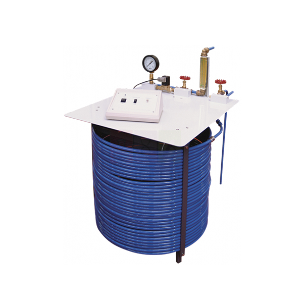
Water Hammer Apparatus
Water Hammer Apparatus (Product Code: SLE/EFM/18) lets students create and measure the pressure surge that travels along a pipe when flowing water is stopped suddenly. At its heart is a 60 m long coil of copper pipe with a solenoid valve at the discharge end; when the valve shuts, an electronic pressure transducer next to it captures the resulting pressure fluctuations. The apparatus serves mechanical and civil engineering courses on unsteady pipe flow, and it is made by Jain Scientific Equipments Pvt Ltd (ScienceLab), Ambala, among its engineering educational equipment for Indian and overseas institutions.
Specifications
| Parameter | Detail |
|---|---|
| Test pipe | Coil of copper pipe, 60 m long |
| Water inlet | Connects to your water supply |
| Fast-closing valve | Solenoid valve at the discharge end of the pipe |
| Flow control | Second adjustable valve at the discharge, downstream of the solenoid valve |
| Bypass valve | At the inlet end, discharging to waste; regulates the mean pipe pressure before the solenoid valve shuts and allows calibration of the pressure transducer |
| Transient measurement | Electronic pressure transducer near the solenoid valve |
| System pressure | Bourdon pressure gauge between the solenoid valve and the downstream control valve |
Typical Use
Students first set a steady flow through the coil with the downstream control valve and adjust the bypass valve to fix the mean pressure, reading it on the Bourdon gauge. Closing the solenoid valve then stops the water almost instantly, and the transducer records a sharp pressure rise followed by a decaying series of oscillations as the wave reflects back and forth along the pipe. From the period of these oscillations and the known pipe length they estimate the pressure-wave speed and compare the peak surge with the value predicted by Joukowsky’s equation.
The long coiled pipe stretches the wave’s travel time so it can be resolved clearly on a recording instrument. Before each session, use the bypass valve and Bourdon gauge to check the transducer calibration, and bleed trapped air from the pipe, as air pockets soften the surge. The rig is a practical choice among engineering educational equipment in India for showing why pipelines need surge protection.
Manufacturer
Jain Scientific Equipments Private Limited builds this apparatus under its ScienceLab label at Ambala in Haryana, where it develops pipe-flow and pressure teaching rigs for colleges and polytechnics. Find out more on our company profile.
Related Fluid Mechanics Equipment
Apparatus that pairs well with water hammer studies:
- Hydraulic Ram Pump — puts the water hammer effect to work to lift water
- Calibration of a Pressure Gauge — explains how the Bourdon gauge on this rig works
- Friction Loss In Pipe — covers steady pipe-flow losses before transients are introduced
- Cavitation In Venturi — another pressure effect students meet in pipe systems
See the rest of the Fluid Mechanics category.
Frequently Asked Questions
How long is the test pipe?
It is a coil of copper pipe 60 m long, which gives the pressure wave a measurable travel time.
Does it need a water supply?
Yes. The inlet connects to your water supply, and the bypass valve at the inlet end discharges to waste, so plan for a drain near the rig.
How are the pressure fluctuations recorded?
An electronic pressure transducer near the solenoid valve measures them. The display or recording instrument is not listed in our current details, so please contact us about readout options.
Can students check the transducer’s calibration?
Yes. The bypass valve sets the mean pipe pressure, which can be read on the Bourdon gauge and used to calibrate the transducer.
What electrical supply is needed for the solenoid valve and transducer?
Supply details are not in our current listing; tell us your mains supply through the contact page.
Is a calibration certificate supplied?
Any certificate requirement should be raised with us when you enquire, as availability depends on the order.
Do you ship outside India?
Yes, we supply institutions in India and international markets; include the destination and quantity in your enquiry.
Request a Quote
To receive a quotation for the Water Hammer Apparatus, contact us or add it to your enquiry cart.
Last updated: 24 September 2026
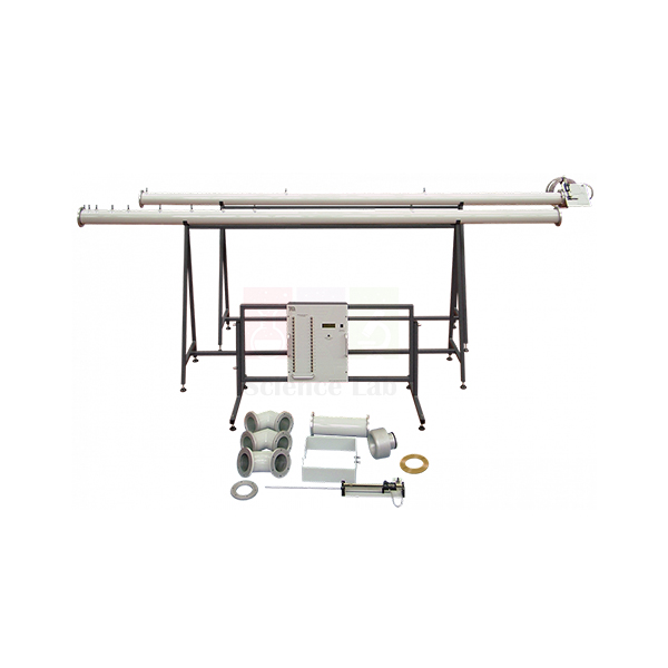
Pipe Flow And Nozzle Kit
Pipe Flow And Nozzle Kit (Product Code: SLE/EFM/19) is an air-flow accessory kit for studying pressure losses in pipes and fittings and for comparing different ways of measuring flow. The pipes connect to a fan inlet so the fan works in suction, drawing air through smooth-walled pipes fitted with many pressure tappings, a Pitot traverse, a nozzle and an orifice plate. It is intended for mechanical and aeronautical engineering practicals, and is manufactured by Jain Scientific Equipments Pvt Ltd (ScienceLab), Ambala, a supplier of lab equipment for college laboratories in India.
Specifications
| Parameter | Detail |
|---|---|
| Test pipes | Two long lengths of smooth-walled pipe with multiple pressure tappings |
| Connection | Pipes connect to the fan inlet, so the fan works in suction for pipe tests |
| Velocity profile | Pitot traverse fitted at the end of one long pipe |
| Nozzle study | Probe in an assembly that moves axially through an additional nozzle to measure its axial pressure profile |
| Flow comparison | Nozzle and orifice plate included for comparing measured flow |
| Fittings | Three: two elbows and a bend, each fitting between the long pipes |
| Pressure readout | Pipe tappings connect to a multiway pressure display |
Kit contents as described:
- Two long smooth-walled pipes with pressure tappings
- Pitot traverse
- Additional nozzle with axially moving probe assembly
- Orifice plate
- Two elbows and one bend
Typical Use
In the first exercise, students read static pressure at each tapping along a straight pipe and plot pressure against distance; the steady gradient gives the friction loss and, with the flow rate, the friction factor. Traversing the Pitot tube across the pipe end then gives the velocity profile, which they integrate to calculate the theoretical flow and compare with the readings from the nozzle and the orifice plate. Moving the probe step by step through the additional nozzle maps its axial pressure profile, showing how pressure converts to velocity as the flow accelerates.
Inserting the two elbows and the bend in turn between the long pipes isolates the extra pressure drop each fitting causes, so students can express it as a loss coefficient. Keep tapping tubes free of kinks, seal every joint well to avoid air leaks, and let the fan settle at each setting before reading.
Manufacturer
This kit is one of the air-flow teaching products developed by Jain Scientific Equipments Private Limited, known in the market as ScienceLab and located in Ambala, Haryana. Visit our company profile to learn about the organisation.
Related Laboratory Equipment
Items that support the same pipe-loss and flow-measurement work:
- Centrifugal Fan Module — a fan unit with a nozzle inlet; ask us to confirm it suits this kit
- Friction Loss In Pipe — the water-flow counterpart for pipe friction studies
- Bernoulli’s Theorem — underpins the nozzle and orifice flow calculations
- U Tube Manometer — for simple differential readings at individual tappings
More equipment is listed in our Fluid Mechanics category.
Frequently Asked Questions
What is included in the kit?
Two long smooth-walled pipes with pressure tappings, a Pitot traverse, an additional nozzle with an axially moving probe, an orifice plate, and three fittings — two elbows and a bend.
Does the kit include a fan?
No fan is listed in the kit; the pipes connect to a fan inlet. Tell us which fan you have, or ask about our Centrifugal Fan Module.
Is the multiway pressure display part of the kit?
The tappings are designed to connect to a multiway pressure display, but the display is not listed among the kit contents. Please contact us to add one.
What pipe diameter and length are used?
Exact dimensions are not in our current product details; ask us for the drawing.
How many flow-measurement methods can be compared?
Three: the Pitot traverse velocity profile, the nozzle and the orifice plate.
Is a calibration certificate available for the orifice plate or nozzle?
Discuss any certificate requirement with us at enquiry stage.
Can you quote for several kits or for export?
Yes. Include the quantity, fan details and delivery location in India or abroad.
Request a Quote
Ask for pricing on the Pipe Flow And Nozzle Kit through our contact page, or add it to the enquiry cart. We serve India and international markets.
Last updated: 24 September 2026
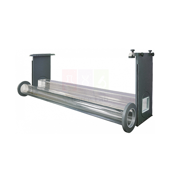
Culvert
Culvert (Product Code: SLE/EFM/20) is a pair of clear culvert models — one of circular section and one of rectangular section — for observing and calculating how water passes through a culvert under a road or embankment. The models let students see both open flow, where the water surface stays free inside the barrel, and orifice flow, where the inlet is submerged and the culvert runs under pressure. The pair is used in civil engineering hydraulics and highway drainage teaching, and is manufactured by Jain Scientific Equipments Pvt Ltd (ScienceLab), Ambala, a laboratory equipment exporter from India.
Key Details
| Parameter | Detail |
|---|---|
| Supplied as | A pair of culvert models |
| Sections | One circular, one rectangular |
| Construction | Clear, so the flow inside each barrel is visible |
| Flow regimes studied | Open flow and orifice flow in a culvert |
| Purpose | Observation and calculation of culvert flow |
Typical Use
One model is set across the channel and the flow is increased gradually. At low flows the inlet is not submerged and the barrel carries a free-surface stream; as the upstream (headwater) level rises and covers the inlet, the culvert switches to orifice-type flow. Students record headwater depth against discharge through both regimes, identify the transition, and compare the measured values with open-channel and orifice equations. Repeating the test with the other model shows how a circular barrel and a rectangular box culvert differ in capacity and in how they fill.
Because the models are clear, air pockets, entrance contraction and the point where the barrel runs full can all be seen directly. Seal the model edges so water cannot slip past, set the channel level, and wait for the headwater to stabilise before each reading.
Manufacturer
Jain Scientific Equipments Private Limited, incorporated under CIN U29309HR2020PTC087597, makes these models under the ScienceLab name in Ambala, Haryana. Its production runs at the licensed factory in HSIIDC Industrial Area, Saha, Ambala (Factory Licence AMB-ONLINE-CHD-J-414). Read more on our company profile.
Related Fluid Mechanics Equipment
Other items used in the same channel and hydraulic-structure practicals:
- Meter Flume — a recirculating channel to test the models in; confirm fitting with us
- Bridge Piers — the other common road-crossing structure studied in flumes
- Sluice Gate with Tappings — compares orifice-type flow under a gate
- Trapezoidal Flume — measures the discharge passing through the culvert
Find more hydraulic models in the Fluid Mechanics category.
Frequently Asked Questions
How many models are in the set?
Two: one culvert of circular section and one of rectangular section.
What is the difference between open and orifice flow here?
In open flow the inlet is not submerged and the water has a free surface inside the barrel; in orifice flow the inlet is covered and the culvert behaves like an orifice under head.
Is a flume needed?
Yes, the models are used in a water channel, and no channel is listed with them. Send your flume details through the contact page so we can advise on fit.
What are the model dimensions?
They are not stated in our current listing; contact us for sizes.
How do I clean clear models?
Rinse with clean water and wipe with a soft cloth; keep solvents away from the clear surfaces.
What warranty is provided?
Warranty terms are confirmed in the quotation; ask us for details.
Request a Quote
To order the Culvert model pair, contact us or use the enquiry cart. Orders are accepted from India and international markets.
Last updated: 24 September 2026
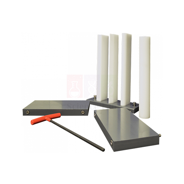
Bridge Piers
Bridge Piers (Product Code: SLE/EFM/21) is a set of four differently profiled bridge piers with a pair of sediment walls, used to show what happens to a river flow as it squeezes past the supports of a bridge. With the piers in a channel, students can observe the increased flow velocity and the streamline curvature between the piers, and watch scouring of the stream bed develop around them. The set is used in civil engineering courses on river hydraulics and bridge design, and is built by Jain Scientific Equipments Pvt Ltd (ScienceLab), Ambala, which makes lab equipment for technical institutes.
Key Details
| Parameter | Detail |
|---|---|
| Piers | Four bridge piers, each with a different profile |
| Sediment walls | One pair, to hold a sediment bed for scour studies |
| Observations | Increased flow velocity and streamline curvature between the piers |
| Bed effects | Scouring of the stream bed |
Typical Use
The sediment walls are placed across the channel to retain a layer of bed material, and one or more piers are set into it. When flow starts, the water speeds up through the narrowed openings between piers and the streamlines bend visibly around each nose. Over time a scour hole forms at the upstream face of each pier where the flow dives down and a horseshoe-shaped vortex lifts sediment. Students swap between the four profiles and compare how deep and how wide the scour becomes, and how strongly the water surface rises upstream.
Introducing a few drops of dye or small floating particles upstream makes the streamline curvature easy to photograph. Level the bed carefully before each run and keep the flow the same between profiles so comparisons are fair. The results connect directly to real decisions about pier shape and foundation depth on bridges over rivers.
Manufacturer
These pier models are made in Ambala, Haryana, by Jain Scientific Equipments Private Limited, the company behind the ScienceLab brand of educational and engineering apparatus. See our company profile for more information.
Related Fluid Mechanics Equipment
Useful companions for river and bridge hydraulics experiments:
- Meter Flume — a recirculating channel to run the piers in; confirm fitting with us
- Culvert — the other road-crossing structure taught alongside bridge piers
- Energy Dissipation — explores protecting a channel bed from high-energy flow
- Lift And Drag — measures the force the flow exerts on submerged bodies
Browse the full Fluid Mechanics range.
Frequently Asked Questions
What does the set include?
Four differently profiled bridge piers and a pair of sediment walls.
What are the sediment walls for?
They hold a bed of sediment in place so students can watch scouring of the stream bed around the piers.
Is sediment or a flume supplied?
Neither is listed with the set. Contact us with your flume details and we will advise on fitting and bed material.
Which pier profiles are included?
The set contains four different profiles; for the exact shapes and dimensions, please ask us.
How should the piers be cleaned after sediment tests?
Rinse off all sediment with clean water, dry the piers and walls, and store them flat to avoid warping.
Can you supply multiple sets for a department?
Yes. Send the quantity and delivery location in India or abroad, and we will quote with lead time.
Request a Quote
For a quotation on Bridge Piers, contact us or add the set to your enquiry cart. We supply India and international markets.
Last updated: 24 September 2026
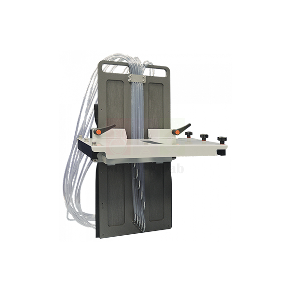
Sluice Gate with Tappings
Sluice Gate with Tappings (Product Code: SLE/EFM/22) is a flume accessory that lets students measure the water pressure acting on the face of a sluice gate. Ten pressure tappings run across the gate face, so the pressure distribution can be read directly and related to the flow rate and the upstream depth. It is intended for use with a flume (not included) in civil engineering and irrigation hydraulics labs, and is manufactured by Jain Scientific Equipments Pvt Ltd (ScienceLab), Ambala, a scientific laboratory equipment manufacturer.
Specifications
| Parameter | Detail |
|---|---|
| Type | Sluice gate for flume experiments |
| Pressure tappings | Ten, across the face of the gate |
| Investigations | Pressure changes across the gate face; variation of pressure with flow rate and depth |
| Used with | A flume, not included |
Typical Use
The gate is installed across the flume with a set opening beneath it, and each tapping is connected to a manometer or pressure display. At a given discharge, students read the upstream depth and the pressure head at every tapping, then plot pressure against position down the gate face. Near the top of the water the readings follow the hydrostatic line, but closer to the gate lip the pressure drops below hydrostatic as the flow accelerates towards the opening — a result that simple textbook assumptions miss.
By changing the flow rate and gate opening, the class sees how the distribution and the total force on the gate change with depth, and can compare the measured force with a hydrostatic estimate. Flush the tapping lines to clear air bubbles before each run, since trapped air gives false readings, and allow the upstream level to settle after every adjustment.
Manufacturer
The gate is produced by Jain Scientific Equipments Private Limited, an Ambala, Haryana manufacturer operating under the trade name ScienceLab. Our company profile explains more about the company and its product lines.
Related Laboratory Equipment
Items used with the gate in the same open-channel practicals:
- Meter Flume — a recirculating flume to install the gate in; confirm fitting with us
- Manometer, Glass — for reading pressure heads at the tappings
- Energy Dissipation — studies the fast flow and jump downstream of control structures
- Trapezoidal Flume — measures the discharge passing under the gate
More channel accessories are in our Fluid Mechanics category.
Frequently Asked Questions
How many pressure tappings does the gate have?
Ten, arranged across the face of the gate.
Is a flume included?
No. The gate is for use with a flume, which is not included. Tell us about your flume via the contact page so we can check compatibility.
What instrument reads the tapping pressures?
A manometer bank or a pressure display is needed; none is listed with the gate, so include your requirement in the enquiry.
Can the gate opening be varied?
The adjustment arrangement is not described in our current details; contact us to confirm how the opening is set.
Is a calibration certificate available?
This is a teaching model; raise any certificate needs with us when enquiring.
What details should I give for a quotation?
Quantity, flume make and width if known, delivery location in India or overseas, and any tender reference.
Request a Quote
To price the Sluice Gate with Tappings, contact us or add it to the enquiry cart. We supply India and international markets.
Last updated: 24 September 2026