- Physics Lab Equipment
- Chemistry Lab Equipment
- Biology Lab Equipment
- Anatomical Lab Equipment
- Learning
- Educational Lab Equipment
- Magnets
- Agriculture
- Astronomy
- Earth Science
- Geography Lab Equipment
- Safety Lab Coat
- Laboratory
- Meteorological
- Electricity & Magnetism
- Heat
- School Lab Equipment
- Lab Glassware
- Science Lab Equipment
- Tvet Lab Equipment
- Robotics Kits Supplier and Manufacturer for Schools India
- Math Lab Equipment Manufacturers and Exporters in Ambala
- STEM Kits Manufacturers and Supplier India
- Engineering Lab Equipment
- Hospital Lab Equipment
- Water, Sanitation & Hygiene Supplies
- Cold Chain, Solar & Communication Equipment
- Nutrition
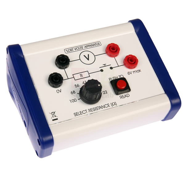
Lost Volts
Lost Volts (Product Code: SLE/EAM/19) is a self-contained apparatus for finding the EMF and internal resistance of a cell by experiment. Seven appropriately rated resistors and a push switch are housed in one unit, so students connect a single source, a voltmeter and an ammeter instead of wiring up a row of loose resistors. It is made by Jain Scientific Equipments Pvt Ltd (ScienceLab), Ambala, India, for school and college laboratories that want a quicker, tidier version of this classic piece of physics practical equipment for CBSE and similar syllabuses.
Specifications
| Parameter | Detail |
|---|---|
| Purpose | Experimental determination of the EMF and internal resistance of a cell |
| Load resistors | Seven appropriately rated resistors housed in the unit |
| Switch | Push switch, reducing unnecessary battery drain and excessive heat in the resistors |
| Source required | 6V DC source of EMF |
| Meters required | One voltmeter and one ammeter |
| Design advantage | Removes the complications of wiring separate resistors |
Typical Use
The name comes from the idea behind the experiment: when a cell drives current through a load, part of its EMF is “lost” across its own internal resistance, so the terminal voltage falls as the current rises. With the 6V DC source connected, the ammeter placed in series and the voltmeter across the source terminals, students press the push switch and record a voltage and current pair with each built-in resistor in circuit. Plotting terminal voltage against current gives a straight line whose intercept on the voltage axis is the EMF and whose gradient gives the internal resistance.
Because the switch only passes current while it is held down, the cell is not left discharging between readings and the resistors do not warm up, which keeps successive readings consistent through a practical period. It is a useful addition to any school physics lab equipment in India where the internal-resistance practical is run by several groups at once. Tip: take each reading promptly after pressing the switch, then release it before changing the load.
Manufacturer
Lost Volts is built by Jain Scientific Equipments Private Limited, a company in Ambala, Haryana that sells its teaching apparatus under the ScienceLab name to schools, colleges and distributors. More about the business and its electricity and magnetism range is on our company profile page.
Related Electricity and Magnetism Equipment
Items that complete the internal-resistance set-up on the bench:
- Digital Voltmeter — reads the terminal potential difference of the source at each load setting
- Digital Ammeter — records the current drawn from the source for the voltage–current graph
- Battery Holder, C — holds cells to build up the source whose internal resistance is being measured
- Stackable Leads — connecting leads for linking the source, meters and unit
- Apparatus for Studying f.e.m. and Internal Battery and Battery Resistance — an alternative apparatus for the same EMF and internal-resistance practical
Browse the complete Electricity and Magnetism range for more circuit and field apparatus.
Frequently Asked Questions
What else do I need to run the experiment?
A 6V DC source of EMF, a voltmeter and an ammeter, plus connecting leads. These are connected to the unit rather than built into it; suitable meters and leads are listed above.
How many load resistors does the unit contain?
Seven, each appropriately rated for the purpose. Individual resistance values are not listed in our current product documentation, so please contact us if your worksheet needs them in advance.
Why is a push switch fitted instead of a toggle switch?
Current flows only while the switch is pressed. This reduces unnecessary drain on the battery and stops excessive heat building up in the resistors between readings.
Can I use a bench power supply as the source?
The unit is intended for a 6V DC source of EMF. A cell or battery is the usual choice, because the aim is to measure that source’s own internal resistance; a well-regulated supply shows very little “lost volts” and gives a less instructive result.
What should an institutional quotation request include?
The product code SLE/EAM/19, the number of units, whether you also need meters, leads or cell holders, and the delivery address. Send these through our contact page.
Is bulk or export supply possible?
Yes. ScienceLab supplies schools, colleges, tender buyers and distributors in India and international markets; quantities and dispatch details are confirmed with each quotation.
Request a Quote
To order Lost Volts for your laboratory, send your requirement through our contact page or add the item to the enquiry cart together with any meters and leads you need, and our team will reply with a quotation.
Last updated: 24 September 2026
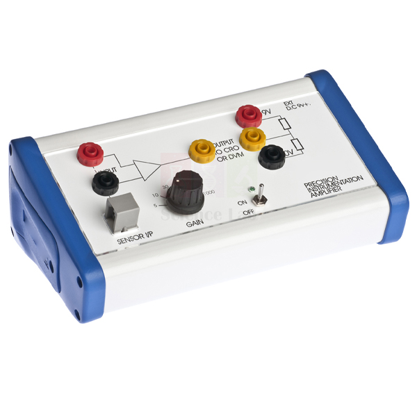
Instrumentation Amplifier
The Instrumentation Amplifier (Product Code: SLE/EAM/20) is a switched-gain precision op-amp unit that boosts the very small signals produced by sensors such as strain gauges, pressure gauges, thermocouples and platinum resistance thermometers until they can be read on an ordinary multimeter. Physics teachers, electronics tutors and engineering instructors use it to turn a sensor experiment into a clear voltage reading. It is produced by Jain Scientific Equipments Pvt Ltd (ScienceLab), Ambala, as part of its range of test and measurement instruments in India for teaching laboratories.
Specifications
| Parameter | Detail |
|---|---|
| Type | Switched-gain precision op-amp |
| Gain settings | 5, 10, 30, 100, 300 and 1000 |
| Sensor input | Telephone type data socket that interfaces with the flying lead of dedicated sensor units |
| Input monitoring | 4mm sockets for monitoring the input signal |
| Output reading | Output voltage measured with a standard multimeter |
| Auxiliary lines | 0V and +9V lines on the front panel for user-designed circuitry |
| Suitable sensors | Strain gauges, pressure gauges, thermocouples, platinum resistance thermometers and similar |
| Dimensions | 190 x 110 x 65mm overall |
Typical Use
Many transducers change their resistance or output voltage by only a tiny amount, far below what a school meter can resolve. The sensor’s flying lead plugs into the data socket, the gain switch is set, and the amplified output is read on a multimeter. A sensible routine is to start on a low gain, confirm the reading is stable, then step up through 30, 100 and beyond until the change of interest is comfortably visible without saturating the output. The 4mm input sockets let students compare the raw signal with the amplified one and work out the actual gain for themselves.
In advanced school physics, polytechnic and first-year engineering classes the unit supports loading experiments with a strain gauge, temperature measurement with thermocouples or resistance thermometers, and pressure sensing. The 0V and +9V lines on the front panel also allow students to build and power small circuits of their own design, which makes the amplifier a flexible choice among lab equipments for technical institutes.
Manufacturer
This amplifier comes from Jain Scientific Equipments Private Limited, trading as ScienceLab, which designs and manufactures physics and electronics teaching apparatus in Ambala, Haryana. The company is a registered MSME enterprise (Udyam UDYAM-HR-01-0003714), and its export consignments are handled under Importer-Exporter Code AAECJ8618A issued by the DGFT. Read more on our company profile.
Related Electricity and Magnetism Equipment
Sensors and meters that work alongside the amplifier in a measurement set-up:
- Strain Gauge — its output lead interfaces directly with this amplifier for strain experiments
- Mini Strain Gauge — a smaller strain-sensing unit for comparative loading work
- Digital Multimeter — reads the amplified output voltage
- Oscilloscope Dual Trace — displays input and output side by side when signals change with time
- Stackable Leads — connects the 4mm monitoring sockets and the meter
More sensors and circuit apparatus are listed in our Electricity and Magnetism category.
Frequently Asked Questions
Which gain settings are available?
Six switched settings: 5, 10, 30, 100, 300 and 1000. Choose the lowest gain that makes the sensor change clearly readable.
How is the output measured?
With a standard multimeter connected to the output. A multimeter is not part of the amplifier; see the related items above if you need one.
Will it work with any sensor?
It is designed for sensors such as strain gauges, pressure gauges, thermocouples and platinum resistance thermometers, and the telephone type data socket is made to accept the flying lead of dedicated sensor units. For a sensor from another source, contact us with its details so we can advise on connection.
What are the 0V and +9V terminals for?
They make the internal supply lines available on the front panel so students can power simple circuits they design themselves.
How large is the unit?
It measures 190 x 110 x 65mm overall, small enough to share a bench with the sensor rig and a meter.
Is a calibration certificate supplied?
Please discuss calibration certificate availability with us when you enquire, as requirements differ between institutions.
Can you quote for a full laboratory order?
Yes. List the amplifier (SLE/EAM/20), matching sensors, meters and quantities, and we will quote for schools, colleges and distributors in India and international markets.
Request a Quote
Add the Instrumentation Amplifier to the enquiry cart along with any sensors you plan to use, or write to us through the contact page for pricing and dispatch details.
Last updated: 24 September 2026
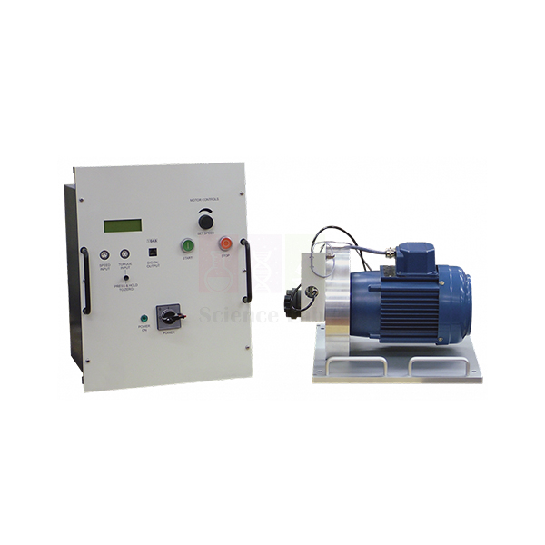
Universal Dynamometer
The Universal Dynamometer (Product Code: SLE/EFM/06) is the shared drive and measuring unit for the Fluid Power machines. It pairs a trunnion-mounted induction motor, which reacts against a strain gauge load cell, with a motor drive and display unit that digitally shows speed, torque and shaft power. Because it couples directly to each machine, students spend their time taking readings rather than fitting belts and pulleys. It is manufactured by Jain Scientific Equipments Pvt Ltd (ScienceLab), Ambala, as part of our test and measuring instrument range for engineering teaching labs.
Specifications
| Parameter | Detail |
|---|---|
| Main parts | Electric dynamometer; motor drive and display unit |
| Dynamometer | Induction motor, trunnion-mounted to move freely against a strain gauge load cell |
| Drive electronics | Variable-speed a.c. inverter drive with signal conditioning |
| Displayed readings | Speed, torque and shaft power (digital) |
| Speed sensing | Inductive sensor on the shaft |
| Torque sensing | Load cell |
| Base plate | Precision-machined, holding the motor and sensors, with location points for accurate, repeatable alignment onto each Fluid Power module |
| Coupling | Jaw-type coupling with a rubber element, common to all Fluid Power machines |
| Controls | Motor stop, start and speed controls on the front of the drive and display unit |
| Instrument power | Outlets on the back supply the instruments provided with the Fluid Power modules |
Typical Use
In a Fluid Power lab the dynamometer is lifted onto whichever module is scheduled for the day — a pump, a compressor or another machine — and dropped onto the base-plate location points so the shaft lines up with the machine’s jaw coupling. Students then set the speed from the front panel and read torque, speed and shaft power directly. Because the motor is trunnion-mounted, the reaction torque on its casing is exactly what the load cell senses, so the displayed torque is the torque delivered to the machine; combining it with the machine’s own flow and pressure readings gives input power, output power and efficiency.
For institutions choosing TVET lab equipment in India, one dynamometer serving many modules is an economical way to build a complete fluid machines laboratory. The instrument outlets on the rear panel mean each module’s gauges draw power from the same unit, cutting down trailing mains leads and keeping the bench tidier and safer. Always press stop before swapping modules, and keep the rubber coupling element in good condition.
Manufacturer
The Universal Dynamometer is built by Jain Scientific Equipments Private Limited in Ambala, Haryana; the company’s products are branded ScienceLab and serve teaching labs at schools, colleges and technical institutes. Read about us on the company profile page.
Related Fluid Mechanics Equipment
Machines whose product data names the Universal Dynamometer as their drive or measuring partner:
- Axial Flow Pump Module — a rotodynamic pump module in the Modular Fluid Power range
- Reciprocating Compressor — the dynamometer measures its speed, torque and absorbed power
- Vane Pump — test direction is set by the dynamometer
- Gear Pump — a second positive displacement pump driven the same way
All hydraulics and fluid machines apparatus is listed in our Fluid Mechanics category.
Frequently Asked Questions
What does the Universal Dynamometer measure?
Shaft speed (by an inductive sensor), shaft torque (by a load cell) and shaft power, all shown on the digital display.
Do I need belts or pulleys to connect it?
No. It drives the Fluid Power machines directly through a jaw-type coupling with a rubber element.
How is alignment kept consistent between modules?
The precision-machined base plate has location points that give accurate, repeatable alignment onto each Fluid Power module.
Can the motor speed be varied?
Yes. The drive and display unit contains a variable-speed a.c. inverter drive, with stop, start and speed controls on the front.
What mains supply and motor rating does it use?
These electrical details are not listed on this page. Please contact us so we can confirm them for your country’s supply.
Is calibration documentation provided for the load cell?
Discuss your calibration or certificate requirements with our team when you enquire.
Do we need one dynamometer per module?
No. It is designed to move between modules, so one unit can serve several machines in turn.
Request a Quote
For a quotation on the Universal Dynamometer on its own or with modules, contact our team or add the items to your enquiry cart. We supply institutions across India and international markets.
Last updated: 24 September 2026
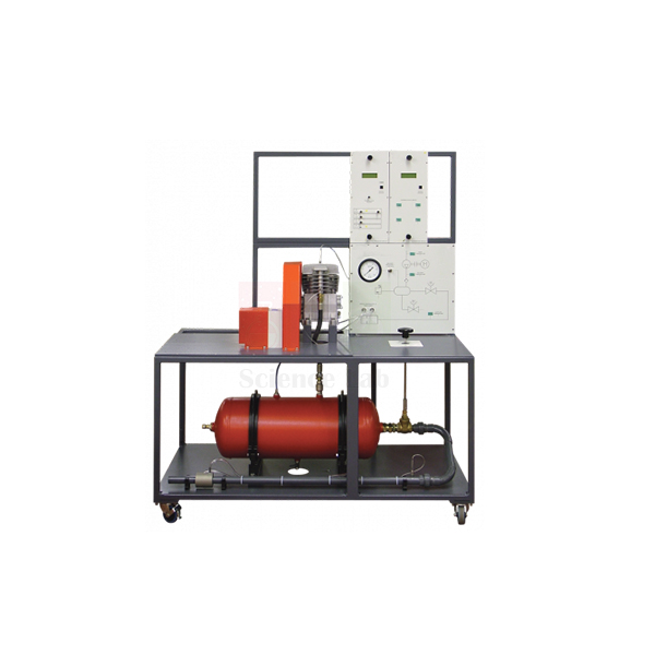
Reciprocating Compressor
The Reciprocating Compressor (Product Code: SLE/EFM/07) is a trolley-mounted test module containing a small compressor, an air receiver and instrumentation, used to show students how a piston compressor turns shaft power into compressed air. A valve and orifice on the receiver outlet let the class set delivery pressure and measure the mass flow of air leaving the system. The module is manufactured by Jain Scientific Equipments Pvt Ltd (ScienceLab), Ambala, as lab equipment for technical institutes, engineering colleges and industrial training centres.
Specifications
| Parameter | Detail |
|---|---|
| Module contents | Small reciprocating compressor, air receiver and instrumentation |
| Mounting | Robust, mobile trolley |
| Air path | Air enters the compressor and is delivered under pressure to the receiver |
| Pressure control | Valve releasing receiver pressure to atmosphere through an orifice; the valve sets receiver pressure and hence flow rate |
| Flow measurement | Orifice for accurate measurement of outlet air mass flow rate |
| Speed | Fully variable up to the maximum allowable for the compressor |
| Power measurement | Speed, torque and power absorbed measured by the separate Universal Dynamometer |
Typical Use
Reciprocating compressors supply the air behind air tools, paint spray equipment, pneumatic actuators and control systems, so this module links directly to what students meet in workshops and plants. In a typical test the compressor runs at a chosen speed while the outlet valve is closed in steps; at each receiver pressure the class records mass flow from the orifice and the power absorbed from the dynamometer. The resulting curves show how the flow the compressor can deliver falls as delivered pressure rises, and let students calculate volumetric efficiency and the power needed per unit of air.
Repeating the series at different speeds shows the effect of running a compressor faster or slower, a practical point for anyone who will later size or operate a plant compressor. As engineering educational equipment for Indian diploma and degree programmes, the trolley mounting lets one module move between rooms. Release receiver pressure fully after each session, keep the orifice clean, and keep hands clear of moving parts while the machine runs.
Manufacturer
This compressor module is produced by Jain Scientific Equipments Private Limited, an Ambala, Haryana manufacturer whose apparatus is sold under the ScienceLab name. The company serves teaching laboratories across engineering and the sciences; visit our company profile to learn more.
Related Fluid Mechanics Equipment
Apparatus that completes a compressor and fluid machines practical:
- Universal Dynamometer — needed to measure speed, torque and power absorbed by the compressor
- Centrifugal Fan Module — a rotodynamic air machine to compare with positive displacement compression
- Calibration of a Pressure Gauge — builds confidence in the pressure readings students rely on
- Vane Pump — a liquid positive displacement machine for the same dynamometer
More modules are listed in the Fluid Mechanics collection.
Frequently Asked Questions
What is included in the Reciprocating Compressor module?
A small compressor, an air receiver and instrumentation, all mounted on a robust mobile trolley.
Is the Universal Dynamometer part of the module?
No. It is a separate unit that measures speed, torque and the power absorbed by the compressor.
How is air flow measured?
Air leaves the receiver through a valve and an orifice; the orifice allows accurate measurement of the outlet air mass flow rate.
How do students change the operating point?
The valve sets the receiver pressure, and hence the flow rate, while compressor speed is fully variable up to its maximum allowable value.
What are the maximum pressure and receiver volume?
These ratings are not published on this page. Please ask our team for the figures before planning experiments.
What warranty applies?
Warranty terms are confirmed on each quotation.
Can you deliver outside India?
Yes. We supply institutions in India and international markets.
Request a Quote
Tell us about your lab through the contact page, or add the Reciprocating Compressor to the enquiry cart, and we will send pricing for the module and any dynamometer you need.
Last updated: 24 September 2026
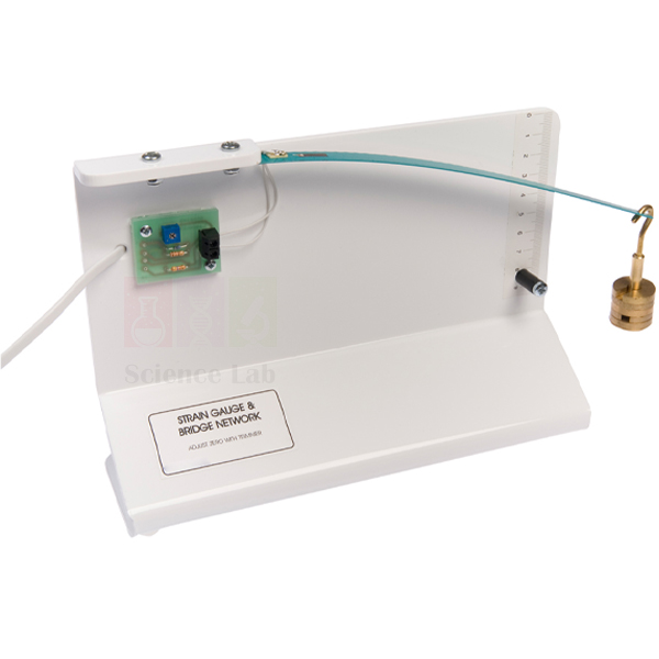
Strain Gauge
The Strain Gauge (Product Code: SLE/EAM/21) lets students watch how the electrical resistance of a gauge changes when the steel blade it is bonded to is bent under strain. The gauge’s terminations are brought out to a resistive bridge network on the main support, and the bridge output lead plugs straight into an Instrumentation Amplifier so the tiny changes become measurable. Manufactured by Jain Scientific Equipments Pvt Ltd (ScienceLab), Ambala, it suits A-level style physics, diploma and engineering lab equipment in India where sensors and materials are taught together.
Specifications
| Parameter | Detail |
|---|---|
| Sensing element | Strain gauge sensor bonded to a steel strip (blade) |
| Circuit | Terminations brought out to a resistive bridge network mounted on the main support |
| Output | Output lead from the bridge interfaces directly with the Instrumentation Amplifier |
| Measurement | Monitors tiny resistance changes when the blade is under strain |
| Spares | Replacement blade/strain gauge available separately |
| Dimensions | 280 x 160 x 65mm overall |
Typical Use
A strain gauge is a fine resistive track that stretches or compresses with the surface it is glued to, changing its resistance very slightly. Placing it in a bridge network turns that small change into an out-of-balance voltage, which the amplifier then raises to a level a multimeter can show. In class, students deflect the blade by increasing amounts, record the amplified output each time and plot output against deflection or load to see how linear the response is. The same set-up opens discussion of how weighing scales, load cells and structural monitoring systems work.
For consistent results, let the bridge settle after switching on, note a zero reading with the blade unloaded, and apply strain gently so the blade is never permanently bent. As a piece of mechanics lab equipment in India it bridges the gap between materials science and electrical measurement, and because the blade and gauge can be replaced separately, the main unit remains usable if a gauge is ever damaged.
Manufacturer
ScienceLab is the brand of Jain Scientific Equipments Private Limited, an Ambala, Haryana manufacturer of sensor, electricity and physics apparatus for teaching laboratories. Visit our company profile to learn how the company works with schools, colleges and distributors.
Related Electricity and Magnetism Equipment
Equipment that completes a strain-measurement experiment:
- Instrumentation Amplifier — the matching amplifier that accepts the bridge output lead directly
- Digital Multimeter — reads the amplified bridge output
- Mini Strain Gauge — a compact alternative for smaller benches or comparison work
- Strain Gauge Trainer — a materials-testing trainer for extending strain studies at engineering level
- Stackable Leads — links the amplifier output to the meter
See all sensors and demonstration units in the Electricity and Magnetism category.
Frequently Asked Questions
Can I read the Strain Gauge without an amplifier?
Not usefully. The resistance changes are tiny, so they need to be monitored by a suitable system such as the Instrumentation Amplifier, whose input accepts the bridge output lead directly.
Is the bridge circuit included?
Yes. The gauge terminations are brought out to a resistive bridge network mounted on the main support, so no separate bridge wiring is needed.
What if the blade or gauge gets damaged?
A replacement blade/strain gauge is available separately. Quote the product code SLE/EAM/21 when you contact us for spares.
How much bench space does it need?
The unit measures 280 x 160 x 65mm overall; allow extra room for the amplifier and meter beside it.
How should the blade be looked after?
Load it gradually, avoid bending it beyond its elastic range, and store the unit flat and dry. Keep the output lead free of sharp kinks.
Do you provide warranty information?
Warranty terms are stated with each quotation; ask our team through the contact page if you need them before ordering.
Request a Quote
For a quotation on the Strain Gauge, with or without the matching amplifier and spare blades, use our contact page or place the items in the enquiry cart. We supply institutions in India and international markets.
Last updated: 24 September 2026

Position Sensor
The Position Sensor (Product Code: SLE/EAM/22) is a precision linear potentiometer whose resistance output changes between 0–5kΩ in step with the position of its slider, so small movements can be converted into an electrical reading. Teachers use it to follow slow movements such as the expansion of metals, and students find almost limitless scope for inventive investigations of their own. It is manufactured by Jain Scientific Equipments Pvt Ltd (ScienceLab), Ambala, a physics instruments supplier in India to schools, colleges and training institutes.
Specifications
| Parameter | Detail |
|---|---|
| Sensor type | Precision linear potentiometer (linear position sensor) |
| Output | Resistance changing between 0–5kΩ with linear position |
| Mounting | Sturdy acrylic base; the whole assembly can be clamped and used in any position |
| Connections | Brought out to 4mm sockets |
| Calibration aid | Bolt-on screw thread jig enables calibration to be carried out easily |
| Dimensions | 180 x 70 x 40mm overall |
Typical Use
Because resistance varies linearly with slider position, the sensor becomes a distance-measuring device once it has been calibrated. Using the bolt-on screw thread jig (similar to the arrangement described in the Advancing Physics notes), students advance the slider by known amounts, record the resistance at each step and draw a calibration graph. They can then attach the slider to a rod being heated, a spring being loaded or any slowly moving object and convert resistance readings straight into displacement.
Classic applications in physics lab equipment in India include measuring the linear expansion of a metal rod, following the extension of a spring, and tracking small movements in project work. The acrylic base can be clamped in a stand horizontally or vertically, and the 4mm sockets accept standard leads to a multimeter or into a potential divider circuit if a voltage output is preferred.
Manufacturer
The sensor is made by Jain Scientific Equipments Private Limited, which operates under the ScienceLab name from Ambala, Haryana and builds measurement and demonstration apparatus for education. For institutional and tender buyers who need vendor registration details, the company’s identifiers are GSTIN 06AAECJ8618A1ZT and LEI 3358004HRD1JIVXKYX49. Our company profile gives further background.
Related Electricity and Magnetism Equipment
Items commonly used with the sensor in expansion and displacement experiments:
- Digital Multimeter — measures the sensor’s resistance output directly
- Expansion Apparatus — provides the heated rod whose expansion the sensor can follow
- Retort Stand — holds the clamped sensor at the height and angle the experiment needs
- Universal Clamp — grips the acrylic base securely on the stand
- Stackable Leads — plug into the 4mm sockets to connect the meter
Find further sensors and circuit apparatus in our Electricity and Magnetism range.
Frequently Asked Questions
What output does the Position Sensor give?
A resistance that changes between 0–5kΩ linearly with position. Read it on an ohmmeter, or wire the sensor as a potential divider to obtain a voltage.
How is it calibrated?
A bolt-on screw thread jig lets you move the slider by known amounts and record the resistance at each step. Please contact us to confirm whether the jig is part of your order.
Can it be mounted vertically?
Yes. The sensor sits on a sturdy acrylic base, and the whole assembly can be clamped and used in any position.
Is it suitable for measuring the expansion of metals?
Yes, monitoring movement such as the expansion of metals is one of its intended uses. The heating apparatus and rod are separate items.
How should the sensor be cared for?
Move the slider smoothly without forcing it past its ends, keep the track free of dust, and avoid loads that could bend the slider.
Is a calibration certificate available?
Certificate availability should be discussed with us at the enquiry stage; in class, the sensor is normally calibrated by the students themselves using the jig.
Do you accept bulk and export orders?
Yes, for schools, colleges and distributors in India and international markets. Share quantities and delivery details with your enquiry.
Request a Quote
Request pricing for the Position Sensor through our contact page, or add it and any stands, clamps and meters to the enquiry cart for a single combined quotation.
Last updated: 24 September 2026
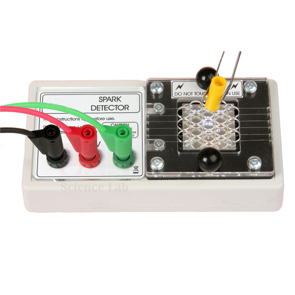
Multi-Wire Spark Detector
The Multi-Wire Spark Detector (Product Code: SLE/EAM/23) gives a memorable, dramatic demonstration of how strongly alpha particles ionise air. A row of fine wires is supported above a metal plate so that the two form electrodes separated by a small air gap; with an EHT supply connected, bringing an alpha source close makes the sparking across the gap increase dramatically, both visibly and audibly. Built by Jain Scientific Equipments Pvt Ltd (ScienceLab), Ambala, it is a teacher-led radiation experiment kit for India’s senior secondary and college physics departments.
Specifications
| Parameter | Detail |
|---|---|
| Construction | Number of fine wires supported above a metal plate, forming two electrodes separated by a small air gap |
| Connections | 4mm terminals for the EHT supply |
| Operating point | Occasional sparks occur when the potential across the gap reaches about 4500V |
| Supply required | EHT power supply capable of providing a negative potential |
| Demonstrates | Ionising properties of alpha particles; their short range and poor penetrating power |
| Indication | Visible and audible sparks |
Typical Use
The teacher raises the EHT voltage slowly until the gap sits just below steady breakdown, at around 4500V, where only the occasional stray spark appears from background ionisation. When an alpha source is brought near the wires, the ion pairs it creates in the air trigger a burst of sparks that the whole class can see and hear. Pulling the source back a few centimetres, or slipping a sheet of paper between source and wires, makes the sparking fall away almost immediately, a direct and convincing way to show the short range and poor penetrating power of alpha radiation.
This demonstration sits well alongside Geiger counter work in any school physics lab equipment in India used for the radioactivity topic. It is intended for teacher operation only: switch off and discharge the EHT supply before touching the terminals, and handle sealed sources with tongs in line with your institution’s radiation safety rules.
Manufacturer
ScienceLab apparatus such as this detector is produced by Jain Scientific Equipments Private Limited of Ambala, Haryana, a manufacturer of physics demonstration equipment for schools and universities. See the company profile for details of the organisation.
Related Electricity and Magnetism Equipment
Supplies and sources needed for the ionisation demonstration, plus a comparison detector:
- EHT Power Supply — an adjustable high-voltage supply; confirm with us that its output arrangement suits the detector
- Sealed Radioactive Source, Americium — an alpha emitter for triggering the sparks
- Sealed Radioactive Source, Strontium — a beta source for contrasting ionising ability with alpha
- Geiger Counter — counts radiation for quantitative range and absorption work
More field and electrostatics apparatus is listed in our Electricity and Magnetism section.
Frequently Asked Questions
What voltage does the detector need?
Sparking begins when the potential across the gap reaches about 4500V, so an EHT power supply is required, and it must be capable of providing a negative potential.
Is a radioactive source included?
No source is described as part of the detector. Alpha sources are separate items and their purchase, storage and use are subject to your local regulations.
Why does an alpha source cause more sparks than other radiation?
Alpha particles have short range but are very effective at ionising air, producing many ion pairs in the gap and triggering breakdown far more readily.
Can students operate it?
Because it runs from an EHT supply and uses radioactive sources, we recommend it as a teacher demonstration with students observing from a safe distance.
How should the wires be looked after?
The wires are fine, so avoid touching or bending them, keep the unit covered and dust-free, and switch off and discharge the supply before any handling.
What details help you prepare an institutional quotation?
The product code SLE/EAM/23, quantity, whether you also need an EHT supply, and the delivery address. Submit them via our contact page.
Request a Quote
Place the Multi-Wire Spark Detector in the enquiry cart or send an enquiry through our contact page; we quote for institutions and distributors in India and international markets.
Last updated: 24 September 2026
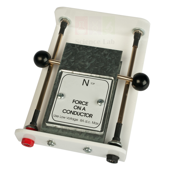
Force on a Conductor Apparatus.
The Force on a Conductor Apparatus. (Product Code: SLE/EAM/24) is a traditional demonstration of the motor effect: a crossbar rests across two side rails between the poles of a magnet, and when current flows through it the crossbar rolls one way or the other under the electromagnetic force. Reversing the current or the magnet reverses the motion, which makes Fleming’s left-hand rule easy to see. It is manufactured by Jain Scientific Equipments Pvt Ltd (ScienceLab), Ambala, and is a straightforward electromagnetic kit for school classrooms in India.
Specifications
| Parameter | Detail |
|---|---|
| Moving conductor | Crossbar that rolls along the side rails |
| Magnet | Clearly labelled poles |
| Connections | 4mm sockets attached to the side rails |
| Operating current | Up to 8A |
| Supply required | Low voltage bench PSU |
| Demonstrates | Force on a current-carrying conductor in a magnetic field |
Typical Use
Connect a low voltage bench power supply to the 4mm sockets on the rails, place the crossbar across them between the magnet poles and switch on: the bar rolls sideways as soon as a sufficient current passes through it. Students predict the direction first using the labelled poles and the direction of conventional current, then check their prediction. Swapping the supply leads sends the bar the other way, and reversing the field would do the same, reinforcing that the force depends on both the field and the current direction.
Raising the current (within the up-to-8A limit) produces a livelier roll, giving a qualitative link between current and force before students meet F = BIL. For a well-rounded physics practical equipment CBSE set, the apparatus pairs naturally with a motor model so learners can see how the same force keeps a coil turning. Keep an ammeter in the circuit, switch off between runs and allow the crossbar to cool, as the high currents involved can warm it.
Manufacturer
Made in Ambala, Haryana by Jain Scientific Equipments Private Limited, whose products are sold under the ScienceLab brand to schools, colleges and distributors. Background on the company is available on our company profile page.
Related Electricity and Magnetism Equipment
Useful partners for a motor-effect lesson:
- Power Supply Variable — a continuously variable AC/DC bench supply for setting the conductor current
- Digital Ammeter — shows the current flowing through the crossbar
- Stackable Leads — connect the supply to the 4mm sockets on the rails
- Aluminium Foil Support Bar — extends the topic to forces between two current-carrying conductors
- Demonstration Electric Motor — shows the same force producing continuous rotation
Explore the wider Electricity and Magnetism collection for more demonstrations.
Frequently Asked Questions
What current does the apparatus need?
It is designed for currents of up to 8A, supplied from a low voltage bench power supply connected to the 4mm sockets on the side rails.
Is a power supply included?
No. A low voltage bench PSU is required and is ordered separately; one option is listed above.
How do students know which way the crossbar should move?
The magnet has clearly labelled poles, so they can apply the left-hand rule using the known field direction and current direction before switching on.
Can the magnet be reversed?
Reversing either the field or the current reverses the force. Changing the supply polarity is the simplest method; please contact us if you need details of how the magnet is mounted.
How should the rails and crossbar be maintained?
Keep the contact surfaces clean and dry so the crossbar makes good electrical contact, and wipe away any tarnish with a soft cloth before a lesson.
Is there a warranty?
Warranty terms are provided with our quotation; ask the sales team if you need them in writing before ordering.
Can you supply several sets for a school or a distributor?
Yes. We supply quantities for schools, colleges and distributors in India and international markets.
Request a Quote
Send us your quantity and delivery location via the contact page, or add the Force on a Conductor Apparatus and a suitable power supply to the enquiry cart to receive one combined quotation.
Last updated: 24 September 2026