- Physics Lab Equipment
- Chemistry Lab Equipment
- Biology Lab Equipment
- Anatomical Lab Equipment
- Learning
- Educational Lab Equipment
- Magnets
- Agriculture
- Astronomy
- Earth Science
- Geography Lab Equipment
- Safety Lab Coat
- Laboratory
- Meteorological
- Electricity & Magnetism
- Heat
- School Lab Equipment
- Lab Glassware
- Science Lab Equipment
- Tvet Lab Equipment
- Robotics Kits Supplier and Manufacturer for Schools India
- Math Lab Equipment Manufacturers and Exporters in Ambala
- STEM Kits Manufacturers and Supplier India
- Engineering Lab Equipment
- Hospital Lab Equipment
- Water, Sanitation & Hygiene Supplies
- Cold Chain, Solar & Communication Equipment
- Nutrition
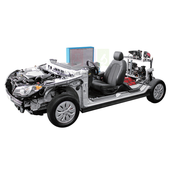
LPI Engine Fault Diagnosis Training Equipment Auto Fault
LPI Engine Fault Diagnosis Training Equipment Auto Fault (Product Code: SLE/ATE/20) is a hybrid powertrain trainer used to teach fault diagnosis on a 1,600cc LPI engine, hybrid motor and automatic transmission in advanced automotive training centres and engineering colleges. A hybrid control unit (HCU) links the ECU, TCM, BMS ECU, MCU and LDC by CAN communication, and a front control panel carries the check terminal and toggle switches. Jain Scientific Equipments Pvt Ltd (ScienceLab) manufactures the training stand and front control panel as the OEM at its own factory in Ambala, India; the LPI engine, hybrid motor and transmission assemblies are sourced production units, not made in Ambala.
Specifications
| Parameter | Detail |
|---|---|
| Powertrain | 1,600cc LPI engine and hybrid motor; engine and A/T automatic transmission |
| Engine style | I4 1.6 (1,591cc) |
| Control network | HCU (hybrid control unit) connected to ECU, TCM, BMS ECU, MCU and LDC by CAN communication |
| Sensors attached | Slant angle sensor, brake boost pressure sensor |
| Hybrid functions shown | Hybrid engine start; power support at idle or slow movement; driving force support when accelerating; energy recovery (battery charge) when decelerating, with brake switch |
| Front control panel | Display panel, ECU circuit, education check terminal, toggle switches; panel displays engine start and engine status |
| Diagnosis | With diagnosis equipment: sensor check, short circuit, failure diagnosis and output power |
| Weight | Approx. 1,300 kg |
| Size | Approx. 4,600 × 1,800 × 1,500 mm |
| Engine / assembly | Sourced production unit (as listed) |
| Product code | SLE/ATE/20 |
| Manufacturer | Jain Scientific Equipments Pvt Ltd (ScienceLab) — OEM |
| Country of origin | India (trainer built in Ambala, Haryana) |
Optional accessories, quoted on request:
- Laptop — CPU Intel Core i7; memory 8GB; USB 3.0; HDMI output; 256GB SSD
- Oscilloscope — 4 channels; bandwidth 20MHz (10MHz on ±50mV range); vertical resolution 12 bits; enhanced vertical resolution 16 bits; pulse width, runt pulse, dropout and windowed functions as listed; maximum post-trigger delay 50 s; maximum pre-trigger delay 10x the per-division time base setting
- Monitor — LED light source; 61 cm (24 inch) screen; resolution 1980 × 1080 as listed; HDMI and D-SUB inputs
What Is the LPI Hybrid Engine Fault Trainer Used For?
Hybrid systems are easiest to teach when students can watch several control units cooperate in real time. On this trainer, the instructor walks the class through each operating mode — hybrid start, idle or creep support, acceleration assist and energy recovery on braking — while the display panel shows engine start and status. Because the HCU, engine ECU, TCM, battery management ECU, motor control unit and LDC share a CAN network, students learn how a fault in one unit can appear as a symptom in another, which is central to modern hybrid diagnosis.
Diagnostic exercises use the education check terminal and toggle switches on the front panel: trainees check sensors, look for short circuits and confirm output power with diagnosis equipment, and the optional oscilloscope captures signals from the CAN-linked units. The unit is a substantial installation for engineering colleges looking for advanced lab equipment for technical institutes, so plan a dedicated bay with suitable floor strength and delivery access.
What to Specify When Ordering
- Whether the optional laptop, oscilloscope and monitor should be included in the quotation
- The number of trainers required for your workshop
- Delivery access and floor space for a unit of approximately 4,600 × 1,800 × 1,500 mm weighing about 1,300 kg
- Your site conditions, so fuel, ventilation and electrical needs can be confirmed with us before installation
OEM Manufacturer
Jain Scientific Equipments Private Limited, which trades as ScienceLab, is the OEM (original equipment manufacturer) of the training stand and front control panel, with its check terminal and toggle switches, of the LPI Engine Fault Diagnosis Training Equipment Auto Fault. These are built at the company's own licensed factory at Saha, Ambala, Haryana, India, and the complete trainer is supplied factory-direct to engineering colleges, training centres, dealers and importers. The 1,600cc LPI engine, hybrid motor and automatic transmission assemblies at its core are sourced production units, not made in Ambala.
The optional laptop, oscilloscope and monitor are standard computer and test equipment that can be quoted alongside it. For repeat orders or replacement parts, ask ScienceLab directly. Our company profile gives more background.
Related Automotive Training Equipment
Trainers that build the knowledge this hybrid unit relies on:
- Electric Vehicle Energy Management Training Equipment — continues the study of battery energy flow in electrified vehicles
- Engine management system (MPI) — engine control fundamentals before moving to hybrid control
- Automotive Engine Fault Diagnosis Simulator Auto Fault — conventional engine and A/T diagnosis for comparison
- Advanced Digital Multimeter — for sensor and short-circuit checks at the education check terminal
Explore the full Automotive Training Equipment range.
Frequently Asked Questions
Is the LPI Engine Fault Diagnosis Training Equipment Auto Fault an LPI or a hybrid trainer?
It is both. The LPI Engine Fault Diagnosis Training Equipment Auto Fault combines a 1,600cc LPI engine (I4 1.6, 1,591cc) with a hybrid motor and automatic transmission, managed by a hybrid control unit that simulates hybrid starting and energy recovery.
Which control units communicate on the CAN network?
On the LPI Engine Fault Diagnosis Training Equipment Auto Fault, the HCU sits at the centre and connects the ECU, TCM, BMS ECU, MCU and LDC through CAN communication, so students can study how a fault in one unit affects the others.
Are the laptop, oscilloscope and monitor included?
No. For the LPI Engine Fault Diagnosis Training Equipment Auto Fault, the laptop, oscilloscope and monitor are listed as options, with their specifications shown on this page. Tell us which options you want and they will be quoted alongside the trainer.
What fuel supply and site preparation does it need?
Fuel, ventilation and electrical requirements for the LPI Engine Fault Diagnosis Training Equipment Auto Fault are not detailed in our product documentation. Please contact us before installation planning so the site needs can be confirmed for your building.
How big is the installation?
The LPI Engine Fault Diagnosis Training Equipment Auto Fault measures approximately 4,600 × 1,800 × 1,500 mm and weighs about 1,300 kg, so it needs a ground-floor bay with suitable floor strength and a clear delivery route.
Who manufactures the LPI Engine Fault Diagnosis Training Equipment Auto Fault?
Jain Scientific Equipments Pvt Ltd (ScienceLab) manufactures the training stand and control panel of the LPI Engine Fault Diagnosis Training Equipment Auto Fault as the OEM at its own licensed factory at Saha, Ambala, India. The LPI engine, hybrid motor and transmission are sourced production units, not made in Ambala; the optional laptop, oscilloscope and monitor are standard equipment.
Is a calibration certificate available for the optional oscilloscope?
Calibration-certificate availability for the optional oscilloscope offered with the LPI Engine Fault Diagnosis Training Equipment Auto Fault depends on the order. Raise it through our contact page at the enquiry stage so it can be discussed before purchase.
Request a Quote
For a factory-direct quotation, installation planning and delivery, contact us or add this trainer to your enquiry cart.
Last updated: 24 September 2026
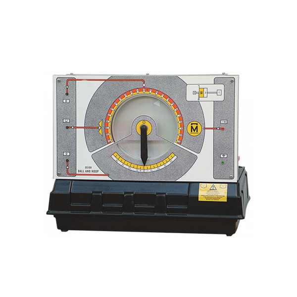
Ball and Hoop Apparatus
Ball and Hoop Apparatus (Product Code: SLE/ETC/06) is an electromechanical servo trainer used to demonstrate position and velocity control, and to model liquid-slop dynamics, in control engineering laboratories. A steel ball rolls inside a hoop that is free to rotate under servomotor control, while transducers output both the hoop position and the ball position. The trainer is manufactured by Jain Scientific Equipments Pvt Ltd (ScienceLab), an OEM manufacturer, at its own factory in Ambala, India.
Key Details
| Parameter | Detail |
|---|---|
| Moving parts | Steel ball that rolls inside a hoop |
| Actuator | Servomotor controlling the hoop, which is otherwise free to rotate |
| Transducers | Outputs for hoop position and ball position |
| Ball behaviour | With the hoop under angular position control, the ball moves like a cylindrical pendulum |
| Modelling use | Study of liquid slop dynamics |
| Application examples | Aircraft missile fuel storage, fuel tankers and industrial pumping systems |
| Product code | SLE/ETC/06 |
| Manufacturer | Jain Scientific Equipments Pvt Ltd (ScienceLab) — OEM |
| Country of origin | India (made in Ambala, Haryana) |
What Is the Ball and Hoop Apparatus Used For?
At its simplest, students close a servo loop on hoop position or speed and study the response. The richer exercises come from the ball: once the hoop is under angular position control, the ball swings like a cylindrical pendulum, adding an oscillating motion that the controller has to take into account.
That pendulum-like motion is a laboratory model of liquid slopping about in a moving container — the same issue designers face with aircraft and missile fuel storage, fuel tankers and industrial pumping systems. Students can try to move the hoop briskly while keeping the ball's swing small, a practical introduction to oscillation control for mechatronics and control courses that rely on engineering educational equipment.
OEM Manufacturer
Jain Scientific Equipments Private Limited, trading as ScienceLab, is the OEM that makes the Ball and Hoop Apparatus at its own licensed factory in Saha, Ambala, Haryana, India. Institutions and distributors buy it straight from the factory, and follow-up needs such as spare parts or additional units can be raised with the same team.
The company is registered as an MSME under Udyam number UDYAM-HR-01-0003714 and holds Importer-Exporter Code AAECJ8618A from the DGFT for its export shipments. Read more on the ScienceLab profile.
Related Control & Process Engineering Trainers
These trainers build on the servo skills practised with the Ball and Hoop Apparatus.
- Ball and Beam Apparatus — stabilising a naturally unstable ball-position system
- Servo Trainer — d.c. servo speed and position control with a clutched reduction gearbox
- Coupled Drives Apparatus — interacting speed and tension control of two motors
- Digital Interface — computer input/output for recording hoop and ball signals
Explore the Control & Process Engineering Trainers category for more.
Frequently Asked Questions
What does the Ball and Hoop Apparatus demonstrate?
The Ball and Hoop Apparatus demonstrates electromechanical servo systems for position and velocity control. Because the ball behaves like a cylindrical pendulum inside the rotating hoop, it also models liquid-slop dynamics for more advanced studies.
What signals does the Ball and Hoop Apparatus provide?
Transducers on the Ball and Hoop Apparatus give outputs of the hoop position and the ball position. Students use them to close the servo loop on the hoop and to observe or control the ball's pendulum-like motion.
What is liquid slop, and why model it with the Ball and Hoop Apparatus?
Liquid slop is the sloshing of liquid in a moving container. The Ball and Hoop Apparatus models it with a ball swinging inside a hoop, which is relevant to aircraft missile fuel storage, fuel tankers and industrial pumping systems.
What drives the hoop of the Ball and Hoop Apparatus?
The hoop of the Ball and Hoop Apparatus is free to rotate but is controlled by a servomotor. Students command the servomotor to set the hoop angle or speed and then watch how the steel ball responds.
Who manufactures the Ball and Hoop Apparatus?
The Ball and Hoop Apparatus is manufactured by Jain Scientific Equipments Pvt Ltd (ScienceLab), the OEM, at its own licensed factory in Saha, Ambala, Haryana, India. Dealers and importers order it factory-direct, with export handled under the company's own IEC.
What should a Ball and Hoop Apparatus quotation request include?
When requesting a Ball and Hoop Apparatus quotation, state the quantity, the delivery city or country, and whether you need a controller or computer interface from the same range. Use our contact page or the enquiry cart to send it.
Request a Quote
Request your Ball and Hoop Apparatus quote through the contact page, or save it to the enquiry cart while you choose related trainers. The manufacturer, Jain Scientific Equipments Pvt Ltd (ScienceLab), replies with the quotation directly.
Last updated: 24 September 2026
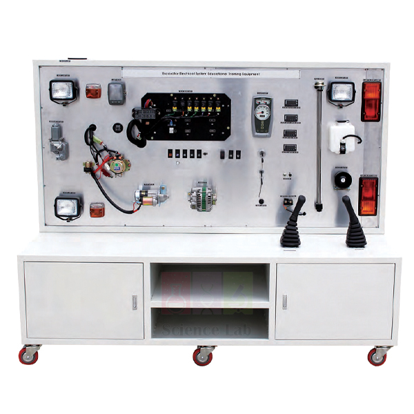
Excavator Electric Circuit Training Simulator
Excavator Electric Circuit Training Simulator (Product Code: SLE/ATE/21) is an open-layout electrical trainer used to teach troubleshooting and inspection of a hydraulic excavator's electric circuit in heavy-machinery and construction-equipment courses. It uses the electronic systems of a Hyundai heavy machinery excavator 555-7K, with parts that are hidden on a real machine laid open so trainees can see their location and operating state. It is supplied by Jain Scientific Equipments Pvt Ltd (ScienceLab), Ambala, India.
Specifications
| Parameter | Detail |
|---|---|
| Basis | Electronic systems of a Hyundai heavy machinery excavator 555-7K |
| Composition | Battery, operating lever, light system, horn, hydraulic lever, instrument panel, starter motor, battery connector, relay, digital meters, etc. |
| Layout | Components normally hidden on an actual machine are opened out to show operating state and location |
| Purpose | Understanding excavator electrical components; troubleshooting and inspection theory and training |
| Size | Approx. 2,000 × 600 × 1,700 mm |
| Training content | Measuring the input/output data in each component |
| Product code | SLE/ATE/21 |
| Supplied by | Jain Scientific Equipments Pvt Ltd (ScienceLab), Ambala, India |
What Is the Excavator Electrical Trainer Used For?
Excavator operators and service technicians meet electrical faults that are hard to trace on a working machine, where wiring runs behind panels and under the cab. On this simulator, trainees work the operating lever, hydraulic lever, horn and lights and watch the instrument panel respond, then measure the input and output at each component to learn what a healthy circuit looks like. With those normal values recorded, instructors can walk them through a logical fault-finding sequence: battery and connector first, then relays, starter motor and switches.
The open layout also helps with component identification for learners who will later work on real machines at construction and mining sites. In a TVET heavy-equipment workshop, pairing it with an operator simulator lets students learn both how the machine is driven and how its electrical system supports those controls. Disconnect the battery connector before changing any wiring on the panel.
Supplier
Jain Scientific Equipments Private Limited, trading as ScienceLab from Ambala, Haryana, India, supplies this excavator circuit simulator to ITIs, polytechnics, heavy-equipment training centres, dealers and importers in India and international markets. Because the trainer is based on the electronic systems of a Hyundai excavator, the company sources it and handles the quotation and delivery for the buyer.
Read more about ScienceLab on the company profile.
Related Automotive Training Equipment
Equipment for a complete heavy-machinery training area:
- Excavator VR Simulator — operator training on the same type of machine
- Wheel Loaders Electric Circuit Training Simulator — the matching electrical trainer for wheel loaders
- Electric Forklift Electric Circuit Training Simulator — extends circuit training to battery-electric material handling
- Digital Multimeter — a handheld meter for students' own input/output measurements
Browse all Automotive Training Equipment.
Frequently Asked Questions
Which excavator is the Excavator Electric Circuit Training Simulator based on?
The Excavator Electric Circuit Training Simulator uses the electronic systems of a Hyundai heavy machinery excavator 555-7K, laid out on an open frame of approximately 2,000 × 600 × 1,700 mm for classroom and workshop training.
Does it include working hydraulics?
No hydraulic pumps or cylinders are listed for the Excavator Electric Circuit Training Simulator. The hydraulic lever is included as part of the electrical control circuit, so students study the electrical side of the machine's hydraulic controls.
What do students measure?
On the Excavator Electric Circuit Training Simulator, students measure the input and output data at each component. Digital meters are part of the composition, and a handheld multimeter is useful so each learner can take independent readings.
What does the simulator weigh?
The weight of the Excavator Electric Circuit Training Simulator is not stated in our current documentation; its size is approximately 2,000 × 600 × 1,700 mm. Contact us for the shipping weight before planning delivery.
Is the battery supplied?
Yes. A battery and battery connector are listed in the composition of the Excavator Electric Circuit Training Simulator, along with the starter motor, relays, instrument panel, light system, horn and operating levers.
Who supplies the Excavator Electric Circuit Training Simulator?
The Excavator Electric Circuit Training Simulator is supplied by Jain Scientific Equipments Private Limited, which trades as ScienceLab from Ambala, Haryana, India, to training institutions, dealers and importers in India and international markets.
Request a Quote
To request a quotation, contact us or add the simulator to your enquiry cart.
Last updated: 24 September 2026
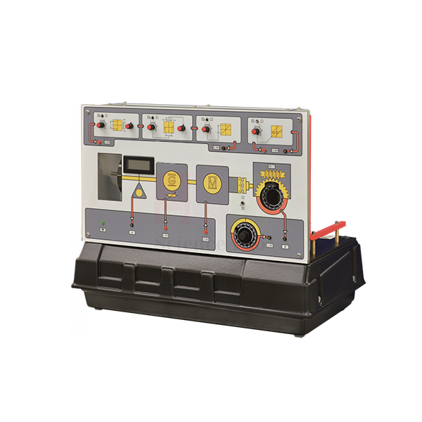
Servo Trainer
Servo Trainer (Product Code: SLE/ETC/07) is a d.c. servo control trainer used to teach position and speed control with typical industrial techniques in electrical and control engineering laboratories. A d.c. servomotor, d.c. generator and flywheel share one shaft, with an electric clutch that engages a 30:1 reduction gearbox for position work and a panel-mounted digital meter that shows speed. Jain Scientific Equipments Pvt Ltd (ScienceLab), an OEM manufacturer, makes it at its own factory in Ambala, India.
Specifications
| Parameter | Detail |
|---|---|
| Drive train | d.c. servomotor, d.c. generator and flywheel mounted on a common shaft |
| Control signal | Analogue, 0 to ±10 V, varying servomotor shaft speed in either direction |
| Speed measurement | Optical sensor, with speed shown on a panel-mounted digital meter |
| Loading | d.c. generator loads the servomotor statically or dynamically |
| Position control | Electric clutch connects or disconnects the shaft to a 30:1 reduction gearbox |
| Position setpoint | Manual control |
| Inertia adjustment | Two extra interchangeable inertia discs (flywheels) supplied |
| Non-linear effect circuits | Block-type circuits adding fully adjustable deadzone (deadband), anti-deadzone, hysteresis and saturation |
| Product code | SLE/ETC/07 |
| Manufacturer | Jain Scientific Equipments Pvt Ltd (ScienceLab) — OEM |
| Country of origin | India (made in Ambala, Haryana) |
What Is the Servo Trainer Used For?
Students usually begin with speed control, driving the servomotor with an analogue signal and reading speed from the optical sensor, then load the shaft with the d.c. generator to see how well a controller rejects disturbances. Engaging the clutch switches to position control through the reduction gearbox, with the manual control providing the position setpoint.
Swapping the interchangeable inertia discs changes the plant, so learners can observe the effect on response and stability. For advanced work, the included block circuits introduce adjustable deadzone, anti-deadzone, hysteresis and saturation — the non-linearities that make real servos misbehave — so classes can study and compensate for them. This breadth makes it a versatile piece of electronics lab equipment for polytechnics and engineering colleges.
OEM Manufacturer
ScienceLab is the trading name of Jain Scientific Equipments Private Limited, the OEM responsible for the Servo Trainer. The company manufactures it at its own licensed factory in Saha, Ambala, Haryana, India, so buyers receive quotations and technical answers from the source rather than from a reseller. Colleges adding more benches later can order matching units directly — ask us for current details. See the company profile for more.
Related Control & Process Engineering Trainers
Other trainers that share the Servo Trainer's focus on motion control:
- Coupled Drives Apparatus — speed and tension control with two belt-coupled motors
- Engine Speed Control Apparatus — speed regulation of a generator-loaded model engine
- Ball and Beam Apparatus — servo-driven stabilisation of an unstable system
- Controller — analogue PID, phase-lead and summing blocks for servo loops
See the complete Control & Process Engineering Trainers category.
Frequently Asked Questions
What control signal does the Servo Trainer use?
The Servo Trainer uses analogue control signals of 0 to ±10 V, which vary the servomotor shaft speed in either direction, so students can drive it from an analogue controller or a suitable interface.
How is speed measured on the Servo Trainer?
An optical sensor on the Servo Trainer measures shaft speed and shows it on a panel-mounted digital meter, so students can read the speed directly while they test their control settings.
What is the gearbox ratio on the Servo Trainer?
The Servo Trainer has a 30:1 reduction gearbox. An electric clutch connects or disconnects the shaft from the gearbox, letting users switch between speed-control studies and position-control studies on the same unit.
Can the inertia of the Servo Trainer be changed?
Yes. The Servo Trainer comes with two extra interchangeable inertia discs (flywheels) for adjusting shaft inertia, so students can compare how a controller performs with lighter and heavier rotating loads.
Which non-linear effects can be added on the Servo Trainer?
The Servo Trainer includes block-type circuits that add fully adjustable deadzone (deadband), anti-deadzone, hysteresis and saturation effects, allowing advanced experiments on how non-linearities affect servo position and speed control.
Who manufactures the Servo Trainer?
Jain Scientific Equipments Pvt Ltd (ScienceLab) manufactures the Servo Trainer as the OEM at its own licensed factory in Saha, Ambala, Haryana, India. Extra inertia discs or other spares can be requested from the manufacturer; ask us about availability.
Is a calibration certificate available for the Servo Trainer's speed meter?
Calibration-certificate availability for the Servo Trainer's panel-mounted digital speed meter should be discussed with us before ordering. Include the requirement in your enquiry through the contact page so it can be confirmed in writing.
Request a Quote
Get a Servo Trainer quotation by contacting us through the contact page or adding it to the enquiry cart. Quotes come directly from the manufacturer, ScienceLab, for institutions, dealers and importers in India and international markets.
Last updated: 24 September 2026
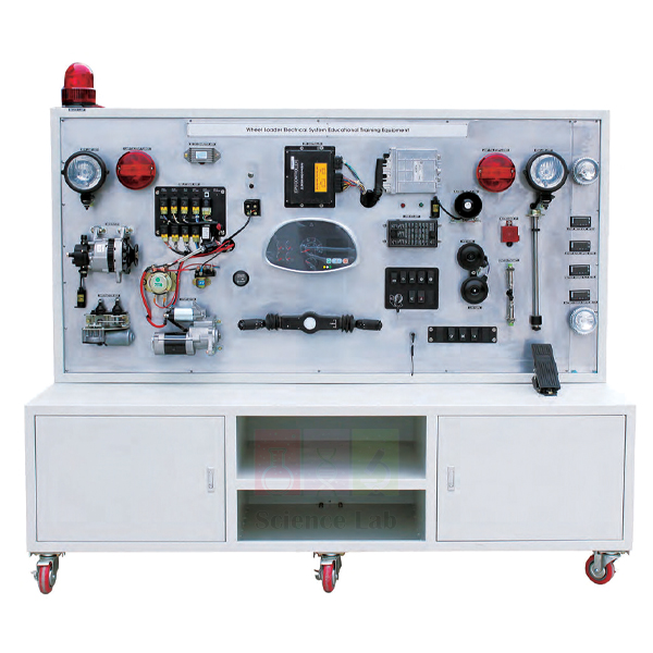
Wheel Loaders Electric Circuit Training Simulator
Wheel Loaders Electric Circuit Training Simulator (Product Code: SLE/ATE/22) is an open-frame electrical trainer used to teach troubleshooting and inspection of a heavy-machinery wheel loader's electric circuit in vocational and engineering workshops. It runs on a DC 24 V battery with an ECU, relays, starter motor, levers and built-in digital meters, so trainees can measure input and output data at each component. It comes from Jain Scientific Equipments Pvt Ltd (ScienceLab), the OEM manufacturer, and is made at its own factory in Ambala, India.
Specifications
| Parameter | Detail |
|---|---|
| Basis | Electric circuit equipment using a heavy machinery wheel loader |
| Power | DC 24 V battery |
| Composition | ECU, battery, operating lever, light system, horn, hydraulic lever, starter motor, battery connector, relay, digital meters |
| Meters | 2 A meter, 2 V meter (as listed), plus digital meters |
| Layout | Parts not visible on an actual machine are opened out to show operating state and location |
| Weight | Approx. 350 kg |
| Size | Approx. 2,000 × 600 × 1,700 mm |
| Training content | Measuring the input/output data in each component |
| Product code | SLE/ATE/22 |
| Manufacturer | Jain Scientific Equipments Pvt Ltd (ScienceLab) — OEM |
| Country of origin | India (made in Ambala, Haryana) |
What Is the Wheel Loader Electrical Trainer Used For?
Wheel loaders run on 24 V electrical systems with an ECU managing many functions, and trainees need to be comfortable with both before they work on machines in quarries, ports or construction sites. On this simulator, students operate the levers, lights and horn and crank the starter motor, reading the built-in meters to build a picture of normal circuit behaviour. Instructors then use that baseline to teach inspection routines and troubleshooting theory: checking the battery and connector, testing relays, and confirming the signals reaching and leaving the ECU.
Because the components are opened out where they can be seen, learners spend less time searching for parts and more time reasoning through a fault. The unit fits naturally into engineering educational equipment for heavy-machinery maintenance courses. Remove the battery connector before altering any wiring, and treat the 24 V battery with the same care as on a real machine.
OEM Manufacturer
ScienceLab is the trading name of Jain Scientific Equipments Private Limited, the OEM (original equipment manufacturer) of the Wheel Loaders Electric Circuit Training Simulator. The trainer is assembled at the company's own licensed factory at Saha, Ambala, Haryana, India, and delivered factory-direct to institutions, dealers and importers.
Buying from the manufacturer means quotations, repeat orders and questions about replacement relays, meters or other parts go to the team that builds the unit — ask us. The company profile explains more about the company.
Related Automotive Training Equipment
Other items for a heavy-machinery electrical lab:
- Excavator Electric Circuit Training Simulator — the same open-circuit approach applied to an excavator
- Electric Forklift Electric Circuit Training Simulator — circuit training for battery-electric forklifts
- Standard Digital Multimeter — for students to take their own readings at each component
- Heavy Duty Vehicles Differential Gear Model — covers the heavy-vehicle driveline side of loader maintenance
More trainers are available in Automotive Training Equipment.
Frequently Asked Questions
What system voltage does the Wheel Loaders Electric Circuit Training Simulator use?
The Wheel Loaders Electric Circuit Training Simulator runs from a DC 24 V battery, which is part of the composition, matching the heavy-machinery electric circuit it reproduces for measurement and fault-finding practice.
Is an ECU included?
Yes. The ECU is listed in the Wheel Loaders Electric Circuit Training Simulator together with the relays, starter motor, operating and hydraulic levers, light system, horn, battery connector and digital meters.
Which meters are fitted?
The Wheel Loaders Electric Circuit Training Simulator has digital meters, listed in the specification as 2 A meter and 2 V meter. For exact meter ranges or counts on the unit you are quoted, please contact us before ordering.
Which wheel loader model is the circuit taken from?
The Wheel Loaders Electric Circuit Training Simulator is described as electric circuit equipment from a heavy machinery wheel loader, without a named model. Ask us if your syllabus or tender requires a specific machine, and we will confirm what can be quoted.
How heavy is it and how much space does it need?
The Wheel Loaders Electric Circuit Training Simulator weighs approximately 350 kg and measures about 2,000 × 600 × 1,700 mm, so it can stand against a workshop wall with students working from the front.
Who manufactures the Wheel Loaders Electric Circuit Training Simulator?
Jain Scientific Equipments Private Limited, trading as ScienceLab, manufactures the Wheel Loaders Electric Circuit Training Simulator as the OEM at its own licensed factory at Saha, Ambala, Haryana, India, and supplies it directly to institutions, dealers and importers.
Request a Quote
Please send an enquiry or add the simulator to your enquiry cart for a quotation straight from the manufacturer.
Last updated: 24 September 2026
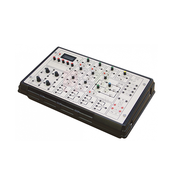
Controller
Controller (Product Code: SLE/ETC/08) is a compact analogue control unit used to assemble industrial-style control loops from patchable circuit blocks in control engineering laboratories. Its front panel carries summing junctions, phase lead, proportional and integral blocks, a complete three-term PID block, a function generator, a digital voltmeter and adjustable potentiometers, plus D/A and A/D interface connections. It is made by Jain Scientific Equipments Pvt Ltd (ScienceLab), an OEM manufacturer, at its own factory in Ambala, India.
Key Details
| Parameter | Detail |
|---|---|
| Construction | Compact unit with analogue electronic circuits connected in blocks |
| Purpose of the blocks | Mimic the important parts of industrial controllers |
| Front panel | Clear diagrams showing each block, each with its own set of connection sockets |
| Blocks | Summing junctions; phase lead; proportional and integral blocks; function generator and digital voltmeter; complete three-term PID (proportional, integral, derivative) block; fully adjustable potentiometers usable as setpoints or attenuators |
| Computer interface | D/A (digital to analogue) and A/D (analogue to digital) connections |
| Use | Blocks are connected in any way the user needs, then linked to the chosen products in the range |
| Product code | SLE/ETC/08 |
| Manufacturer | Jain Scientific Equipments Pvt Ltd (ScienceLab) — OEM |
| Country of origin | India (made in Ambala, Haryana) |
What Is the Controller Unit Used For?
Instead of a sealed box, students see each function of an industrial controller as a separate block and connect the blocks through their sockets to build the structure they want — from simple proportional control to full PID with a phase-lead stage. The function generator provides test signals, and the digital voltmeter lets them read signal and setpoint values directly.
Once built, the loop is connected to a plant from the range and tuned on real hardware. The D/A and A/D connections also let a computer take part, so the same unit supports comparisons between analogue and digital control. It is a natural companion when institutions assemble engineering lab equipment for control practicals.
OEM Manufacturer
The Controller is manufactured by Jain Scientific Equipments Private Limited, which does business as ScienceLab, as the original equipment manufacturer. Assembly takes place at its own licensed factory in Saha, Ambala, Haryana, India, and units are supplied factory-direct to institutions, dealers and importers.
Procurement teams completing vendor forms can use the company's GSTIN, 06AAECJ8618A1ZT, and its Legal Entity Identifier, 3358004HRD1JIVXKYX49. The ScienceLab profile has more company information.
Related Control & Process Engineering Trainers
The Controller connects to products in this range; these trainers give it a real plant to control.
- Servo Trainer — d.c. servo speed and position plant with non-linear effect circuits
- Coupled Tanks Apparatus — liquid-level plant for PID tuning practice
- Thermal Control Process Apparatus — temperature plant with adjustable measurement lag
- Digital Interface — interface-only alternative when the controller blocks are not needed
Browse every trainer in the Control & Process Engineering Trainers category.
Frequently Asked Questions
What blocks are on the Controller?
The Controller (SLE/ETC/08) includes summing junctions, phase lead, proportional and integral blocks, a function generator and digital voltmeter, a complete three-term PID block, and fully adjustable potentiometers that can act as setpoints or attenuators.
Does the Controller connect to a computer?
Yes. The Controller includes an interface with D/A (digital to analogue) and A/D (analogue to digital) connections, so a computer can exchange signals with the circuit blocks and with the apparatus connected to them.
Which apparatus can the Controller be used with?
The Controller is intended to connect to the user's chosen products in the same control engineering range, such as the servo, tank and process trainers. For equipment from other ranges, send us its signal details so compatibility can be checked.
What is the difference between the Controller and the Digital Interface?
The Controller contains analogue controller blocks plus a D/A and A/D interface, while the Digital Interface provides only the interface part. Choose the Controller when students should build analogue loops, and the Digital Interface when control runs entirely on a computer.
Who manufactures the Controller?
The Controller (SLE/ETC/08) is manufactured by Jain Scientific Equipments Pvt Ltd (ScienceLab), the OEM, at its own licensed factory in Saha, Ambala, Haryana, India. Buyers equipping several benches can order matching units, with quotations handled by the manufacturer.
Is a calibration certificate available for the Controller's digital voltmeter?
Calibration-certificate availability for the digital voltmeter in the Controller should be discussed with us before ordering. Mention it in your enquiry via the contact page so the requirement is reviewed and answered in the quotation.
Request a Quote
Ask for a Controller quotation through the contact page or add it to the enquiry cart along with the trainers it will drive. The manufacturer, Jain Scientific Equipments Pvt Ltd (ScienceLab), sends the quote directly.
Last updated: 24 September 2026
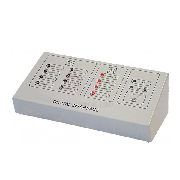
Digital Interface
Digital Interface (Product Code: SLE/ETC/09) is a computer interface unit used to connect laboratory control apparatus to a PC for signal monitoring and computer-based control in engineering laboratories. It converts analogue signals from equipment into digital form for the computer, and turns the computer's digital outputs back into analogue control signals, handling up to eight inputs and four outputs. It is manufactured by Jain Scientific Equipments Pvt Ltd (ScienceLab), an OEM manufacturer, at its own factory in Ambala, India.
Specifications
| Parameter | Detail |
|---|---|
| Inputs | Monitors up to eight input signals (analogue inputs converted to digital signals for a computer) |
| Outputs | Controls up to four output signals (digital signals from a computer converted to analogue) |
| Compatibility | For use with most products in the Control Engineering range; also works with other compatible laboratory equipment |
| Role | Alternative to the Controller when the user only needs the interface part |
| Product code | SLE/ETC/09 |
| Manufacturer | Jain Scientific Equipments Pvt Ltd (ScienceLab) — OEM |
| Country of origin | India (made in Ambala, Haryana) |
What Is the Digital Interface Used For?
Many control courses now implement controllers in software. The Digital Interface makes that possible on physical hardware: sensor signals from an apparatus are digitised for the computer, the control algorithm runs on the PC, and the resulting outputs are converted back into analogue signals that drive pumps, heaters or motors.
With eight inputs, several measurements — for example two tank levels plus a flow reading — can be monitored at once, while four outputs cover experiments with more than one actuator. Choosing the Digital Interface instead of the Controller suits labs that already have their own analogue controllers, or that want benches centred purely on computer control, and it slots easily into existing engineering lab equipment in India and abroad.
OEM Manufacturer
Jain Scientific Equipments Private Limited, the company behind the ScienceLab brand, is the OEM of the Digital Interface and produces it at its own licensed factory in Saha, Ambala, Haryana, India. Because the maker supplies it directly, institutions can ask the same team about matching it to existing apparatus, adding units for more benches or obtaining replacement parts. The ScienceLab profile explains more about the company.
Related Control & Process Engineering Trainers
Apparatus from this range that the Digital Interface can work with, plus its analogue alternative:
- Controller — analogue controller blocks together with a D/A and A/D interface
- Coupled Tanks Apparatus — level and flow signals for computer-based level control
- Servo Trainer — speed and position signals for digital servo control
- Ball and Beam Apparatus — beam-angle and ball-position signals for digital stabilisation
The full range is in the Control & Process Engineering Trainers category.
Frequently Asked Questions
How many channels does the Digital Interface have?
The Digital Interface lets the user monitor up to eight input signals and control up to four output signals, converting between the analogue signals of the apparatus and the digital signals of a computer.
What equipment works with the Digital Interface?
The Digital Interface is for use with most products in the Control Engineering range and will also work with other compatible laboratory equipment. Share the signal details of any other apparatus with us so compatibility can be confirmed before you order.
Should I choose the Digital Interface or the Controller?
Choose the Digital Interface when you only need the interface part, because it is designed as an alternative to the Controller for exactly that case. Pick the Controller if students also need analogue blocks such as PID and phase lead.
What does the Digital Interface convert?
The Digital Interface converts analogue inputs from laboratory equipment into digital signals for a computer, and converts digital signals from the computer into analogue signals that control other equipment.
Who manufactures the Digital Interface?
Jain Scientific Equipments Pvt Ltd (ScienceLab) is the OEM manufacturer of the Digital Interface, which is made at its own licensed factory in Saha, Ambala, Haryana, India. Additional interfaces for extra benches can be quoted by the same manufacturer.
Is software supplied with the Digital Interface?
Software is not listed in the Digital Interface product details. Tell us which computer platform and control software your lab uses when you enquire, and the manufacturer will confirm what can be offered with the unit.
Request a Quote
To obtain a Digital Interface quotation, contact us via the contact page or place it in the enquiry cart. Quotations come straight from the manufacturer, ScienceLab, for India and international markets.
Last updated: 24 September 2026
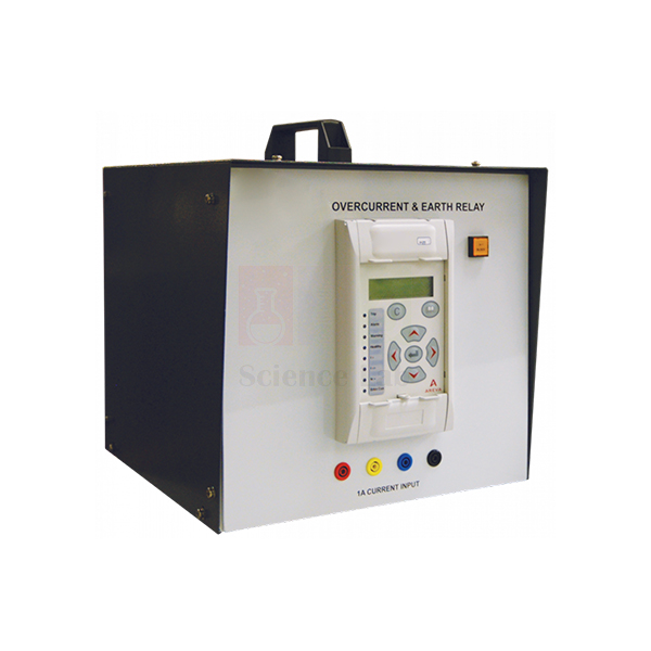
Overcurrent And Earth Fault Relay
Overcurrent And Earth Fault Relay (Product Code: SLE/EPS/01) is a programmable protection-relay module used to teach how overcurrent and earth-fault protection is set, tested and verified in power system and electrical engineering laboratories. It is based on the Micom P122 industrial relay and provides three independent three-phase overcurrent and earth-fault stages, the first selectable from 12 IDMT curves. It is supplied by Jain Scientific Equipments Pvt Ltd (ScienceLab), Ambala, India.
Specifications
| Parameter | Detail |
|---|---|
| Relay basis | Micom P122 industrial relay |
| Programming | Keypad and display on the relay module; or relay support software on a suitable computer |
| Three-phase earth and overcurrent | Three independent stages; first stage selectable from any of 12 IDMT curves; remaining stages with a direct time characteristic |
| Restricted earth fault | High impedance |
| Thermal protection | Thermal overload |
| Negative-phase sequence overcurrent | Two independent stages |
| Other functions | Broken conductor detection; selectable blocking; undercurrent; circuit monitoring |
| Records | Trend, fault and disturbance records |
| Test arrangement | Connected to fault circuits set up on a Protection and Relay Test Set; most tests use single relays |
| Product code | SLE/EPS/01 |
| Supplied by | Jain Scientific Equipments Pvt Ltd (ScienceLab), Ambala, India |
What Is the Overcurrent and Earth Fault Relay Used For?
Protection relays decide when a circuit breaker must trip, and setting them correctly is a core skill for power engineers. In the lab, the lecturer or students build a fault circuit on the Protection and Relay Test Set, program the relay module for the test using its keypad and display (or from a computer running the relay support software), and then apply the fault. Measuring how quickly the relay operates at different fault currents lets students plot its real characteristic and compare it with the selected IDMT curve.
Because the first stage offers 12 IDMT curves and the remaining stages have a direct time characteristic, one relay can show how the choice of curve changes tripping times and how separate stages are graded against each other. Further exercises cover restricted earth fault, thermal overload, negative-phase-sequence protection and broken conductor detection, while the stored fault and disturbance records let students review each event after the test.
What to Specify When Ordering
- Whether you already have a Protection and Relay Test Set or need a test arrangement discussed with us.
- Whether a computer and the relay support software should be arranged for programming.
- Other protection relays for the same lab, such as differential, distance or directional types.
- Number of relay modules for your student groups.
Supplier
Jain Scientific Equipments Private Limited, trading as ScienceLab, sources and supplies the Overcurrent And Earth Fault Relay module to electrical engineering colleges, polytechnics, power-sector training institutes, dealers and importers in India and international markets. It can be quoted together with other relay modules and power system trainers as a single laboratory package.
Company background is available on the ScienceLab profile.
Related Power & Energy Systems Trainers
A protection laboratory typically combines several relay types with switching equipment:
- Directional/Non-Directional Overcurrent Relay — adds direction sensing for ring and parallel feeders.
- Differential Protection Relay — unit protection for transformers and machines.
- Distance Protection Relay — impedance-based protection for transmission lines.
- Circuit Breaker Trainer — shows the switching device that a relay trips.
Explore all Power & Energy Systems Trainers.
Frequently Asked Questions
Which relay is the Overcurrent And Earth Fault Relay module based on?
The Overcurrent And Earth Fault Relay module is based on the Micom P122 industrial relay, so students set and test an industrial protection relay rather than a simplified teaching device.
How many IDMT curves does the Overcurrent And Earth Fault Relay offer?
The Overcurrent And Earth Fault Relay offers three independent three-phase earth and overcurrent stages. The first stage is selectable from any of 12 IDMT curves, and the remaining stages have a direct time characteristic.
How is the Overcurrent And Earth Fault Relay programmed?
The Overcurrent And Earth Fault Relay is programmed with the keypad and display on the relay module, or with the relay support software on a suitable computer. Settings are entered before each test on the fault circuits.
What else is needed to test the Overcurrent And Earth Fault Relay?
The Overcurrent And Earth Fault Relay is connected to fault circuits set up on a Protection and Relay Test Set, and most tests are performed with single relays. Ask us through the contact page about a suitable test arrangement.
Who supplies the Overcurrent And Earth Fault Relay?
The Overcurrent And Earth Fault Relay is supplied by Jain Scientific Equipments Pvt Ltd (ScienceLab), Ambala, Haryana, India, to engineering institutions, dealers and importers in India and international markets, alone or with other protection relays.
Is a calibration certificate available for the Overcurrent And Earth Fault Relay?
A calibration or test certificate for the Overcurrent And Earth Fault Relay module is not listed as standard. If your laboratory needs such documentation, please discuss it with us through the contact page before ordering.
Request a Quote
Send your requirement for the Overcurrent And Earth Fault Relay through the contact page or add it to the enquiry cart.
Last updated: 24 September 2026