- Physics Lab Equipment
- Chemistry Lab Equipment
- Biology Lab Equipment
- Anatomical Lab Equipment
- Learning
- Educational Lab Equipment
- Magnets
- Agriculture
- Astronomy
- Earth Science
- Geography Lab Equipment
- Safety Lab Coat
- Laboratory
- Meteorological
- Electricity & Magnetism
- Heat
- School Lab Equipment
- Lab Glassware
- Science Lab Equipment
- Tvet Lab Equipment
- Robotics Kits Supplier and Manufacturer for Schools India
- Math Lab Equipment Manufacturers and Exporters in Ambala
- STEM Kits Manufacturers and Supplier India
- Engineering Lab Equipment
- Hospital Lab Equipment
- Water, Sanitation & Hygiene Supplies
- Cold Chain, Solar & Communication Equipment
- Nutrition
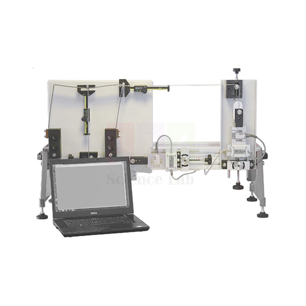
Plastic Bending of Portals
Plastic Bending of Portals (Product Code: SLE/EG/26) is a structural experiment in which a specimen portal frame is loaded beyond its elastic limit until plastic hinges form and it collapses. Load cells apply and measure vertical, horizontal or combined loads through cables held at 90 degrees to the portal, while precision indicators track how the frame deforms. The apparatus shows how a building can yield yet still carry load long enough for people to leave safely. It is manufactured by Jain Scientific Equipments Pvt Ltd (ScienceLab), Ambala, an engineering lab equipment manufacturer supplying civil and structural engineering departments.
Key Details
| Parameter | Detail |
|---|---|
| Type | Plastic collapse experiment for portal frames |
| Specimen mounting | Portal frame fitted to fixing blocks that simulate fixed foundations |
| Load application | Load cells apply and measure the load through cables at 90 degrees to the portal, preserving load direction as the portal deforms |
| Load cases | Vertical, horizontal or combined loads |
| Deformation measurement | Precision indicators |
| Behaviour studied | Elastic region, plastic region with permanent deformation, formation of plastic hinges and plastic collapse |
| Analysis outcome | Interaction between vertical and horizontal loads and an interaction diagram to predict the failure mode |
Typical Use
Before loading, students predict the collapse loads for the chosen load case using textbook plastic analysis, identifying where hinges should form in a fixed-base portal. They then increase load through the cable-and-load-cell system, recording force and deformation. The response starts out linear, then flattens as the first hinge forms and the frame begins to deform permanently, until a mechanism develops and the portal can take no more load. Because the cables stay at 90 degrees to the portal, the load direction is preserved even as the frame sways, so the measured collapse load can be compared fairly with prediction.
Repeating the test with vertical only, horizontal only and combined loads lets the class plot an interaction diagram and see which failure mode governs for each combination. This builds real understanding of ductility and reserve strength, and why designers value them. The rig is well suited to final-year undergraduate and postgraduate structures work and to technical institutes teaching limit-state concepts.
Manufacturer
ScienceLab is the trading name of Jain Scientific Equipments Private Limited (CIN U29309HR2020PTC087597), an Ambala, Haryana company. Its apparatus is made at the licensed factory at 449, HSIIDC Industrial Area, Saha, Ambala (Factory Licence AMB-ONLINE-CHD-J-414). Read more on our company profile.
Related Laboratory Equipment
Experiments and tools that build on the same plastic-analysis topic:
- Plastic Bending Of Beams — introduces hinge formation and shape factor on single beams before moving to frames
- Bending Moments In A Portal Frame — covers the elastic bending moment distribution in a portal
- Frame Deflections And Reactions — measures sway and base reactions of frames within the elastic range
- Caliper Vernier (Metal) — for measuring the specimen cross-section used in plastic moment calculations
Our General Products category holds the full structures range.
Frequently Asked Questions
Why are the loads applied through cables?
Each load cell pulls through a cable held at 90 degrees to the portal, which keeps the load direction constant as the frame deforms and sways.
Can a specimen portal be reused?
Once taken into the plastic region it is permanently deformed, so each specimen serves one collapse test. Ask us about spare specimen portals when you order.
Which load combinations can be tested?
Vertical, horizontal or combined loads, allowing students to build an interaction diagram and predict the failure mode.
What load capacity and specimen material are used?
These values are not included in our current product description. Please contact us for the technical sheet.
Is a calibration certificate available for the load cells?
Availability should be discussed with us at the enquiry stage.
What should a university purchase enquiry include?
The number of rigs, spare specimens required, delivery location and any tender reference. Warranty terms are given with the quotation.
Do you export this apparatus?
Yes, it is supplied to institutions in India and international markets.
Request a Quote
For a price on Plastic Bending of Portals and spare specimens, reach us through the contact page or add the item to the enquiry cart.
Last updated: 24 September 2026
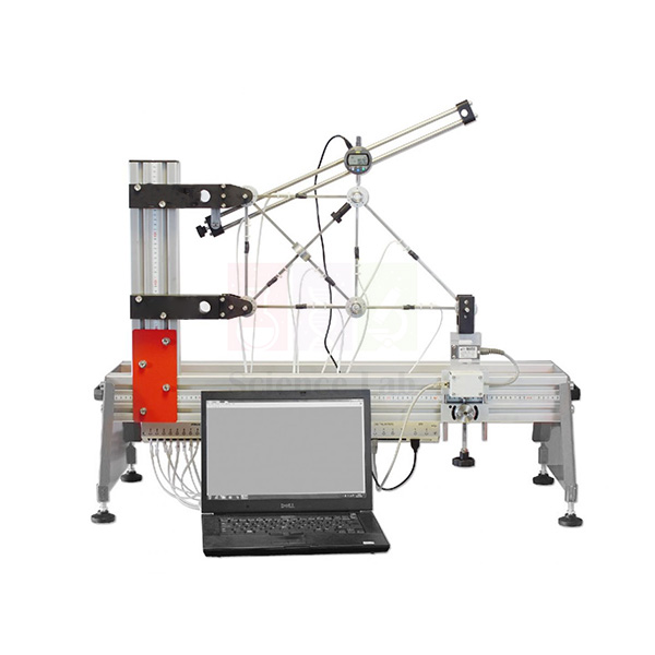
Redundant Truss Next Generation Structures
Redundant Truss Next Generation Structures (Product Code: SLE/EG/04) is a truss experiment used to compare a statically determinate frame with a statically indeterminate one in university and engineering college structures labs. Strain gauges on every member, a precision deflection indicator and an extra ‘redundant’ member engaged by a thumbscrew let students test both cases on the same frame. It is manufactured by Jain Scientific Equipments Pvt Ltd (ScienceLab), an OEM manufacturer, at its own factory in Ambala, India, as engineering educational equipment for structural analysis courses.
Key Details
| Parameter | Detail |
|---|---|
| Type | Redundant truss experiment (determinate and statically indeterminate cases) |
| Supports | Two: one allows rotation only; the other allows rotation and translation |
| Load application | Hand-operated load cell assembly that applies and measures the load at the free-end Joint Boss |
| Member force measurement | Strain gauges on each truss member |
| Deflection measurement | Precision indicator measuring the framework deflection |
| Redundant member | Extra member engaged and disengaged with a simple thumbscrew |
| Data connection | Strain gauges connect to a strain gauge amplifier, which connects to the interface hub of the Structures Platform for computer display and data acquisition |
| Analysis | Textbook truss equations for the determinate case; a more advanced method such as the strain-energy method for the indeterminate case |
| Product code | SLE/EG/04 |
| Manufacturer | Jain Scientific Equipments Pvt Ltd (ScienceLab) — OEM |
| Country of origin | India (made in Ambala, Haryana) |
What Is the Redundant Truss Used For?
The practical runs in two halves. With the redundant member disengaged, the frame is statically determinate: students apply load at the Joint Boss with the hand-operated load cell, read the strain in each member and convert it to member force, then check the values against a method-of-joints calculation. They also note the deflection on the precision indicator. This first half confirms the reliability of the textbook equations and the accuracy of the experimental results.
Turning the thumbscrew then brings the extra member into action and the same loads are repeated. Now the forces can no longer be found from equilibrium alone, so students predict them with the strain-energy method and compare deflection for both cases, seeing how the redundant member shares load and stiffens the frame. For colleges buying engineering lab equipment in India, it bridges determinate and indeterminate structures in one bench-top module.
What to Specify When Ordering
- Whether you already have the Structures Platform, whose interface hub is needed for computer display and data acquisition (it is a separate item).
- Whether the strain gauge amplifier should be quoted with the truss — we will confirm exactly what your order includes.
- The computer you will use for display and logging through the Structures Platform.
- The number of truss units and any other structures modules to be quoted together.
OEM Manufacturer
Jain Scientific Equipments Private Limited, trading as ScienceLab, is the OEM (original equipment manufacturer) of this redundant truss and produces it at its own licensed factory at Saha, Ambala, Haryana, India. Universities and colleges building a structures laboratory can buy it factory-direct alongside the rest of the range, and questions about the frame, load cell assembly or replacement parts go straight to the people who build it — ask us. Company details are on our company profile.
Related Laboratory Equipment
Items used with, or studied alongside, this truss module:
- Structures Platform — houses the interface hub through which the strain readings reach a computer.
- Continuous and Indeterminate Beams — the same determinate-to-indeterminate idea applied to beams.
- Two Pinned Arch — another structure where a measured reaction is compared with theory.
- Bending Stress In a Beam — practises strain-gauge measurement on a simpler member.
For more structures apparatus, open our General Products listing.
Frequently Asked Questions
What makes the truss ‘redundant’?
The Redundant Truss Next Generation Structures frame has an extra member that a simple thumbscrew engages. With it engaged, the frame becomes statically indeterminate, so member forces can no longer be found from equilibrium alone and need a method such as strain energy.
How are member forces measured?
Each member of the Redundant Truss Next Generation Structures carries strain gauges. Their signals pass to a strain gauge amplifier, which connects to the interface hub of the Structures Platform for computer display and data acquisition.
Does it need the Structures Platform?
Yes, for computer display and data acquisition. The Redundant Truss Next Generation Structures connects through a strain gauge amplifier to the Structures Platform interface hub, and the platform is listed as a separate item.
Is the strain gauge amplifier included?
The current Redundant Truss Next Generation Structures listing does not confirm whether the strain gauge amplifier is included. Please contact us before ordering and we will state exactly which parts your quotation covers.
What is the load capacity of the load cell?
The load capacity of the hand-operated load cell assembly on the Redundant Truss Next Generation Structures is not stated in our current text. Ask us through the contact page for the datasheet of the unit you are quoted.
Who manufactures the Redundant Truss Next Generation Structures?
The Redundant Truss Next Generation Structures is manufactured by Jain Scientific Equipments Pvt Ltd (ScienceLab), the OEM, at its own licensed factory at Saha, Ambala, Haryana, India. Quotations for single modules or a full structures laboratory come directly from the manufacturer.
Can you quote for a full structures laboratory?
Yes. Send the list of structures modules, including the Redundant Truss Next Generation Structures and the Structures Platform, with quantities and your delivery location in India or international markets, and we will prepare one quotation.
Request a Quote
Pricing for this redundant truss comes direct from the manufacturer: use our contact page, or add it to your enquiry cart together with the Structures Platform.
Last updated: 24 September 2026
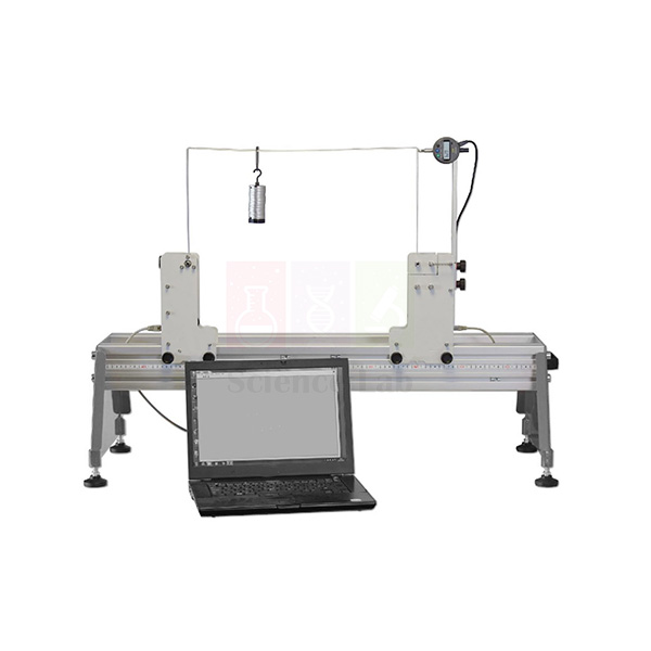
Frame Deflections And Reactions
Frame Deflections And Reactions (Product Code: SLE/EG/05) lets students load a portal-type frame and measure how it sways and what reactions develop at its base. One of two frames is fitted between two supports; load cells in the supports read the bending moment and horizontal reaction at the foot of each upright, and a precision indicator records sideways deflection at the beam-to-upright junction. A Vernier caliper is included for cross-section measurement. The module is made by Jain Scientific Equipments Pvt Ltd (ScienceLab), Ambala, as structures lab equipment for college and university civil engineering courses.
Key Details
| Parameter | Detail |
|---|---|
| Type | Frame sway, deflection and support reaction experiment |
| Frames | Choice of two frames, fitted between two supports |
| Loading | Vertical loads on the beam member; both frame beams can be loaded anywhere along their length |
| Sway measurement | Precision indicator at the junction of the beam and the upright |
| Reaction measurement | Load cells in the supports measure bending moment and horizontal reaction at the base of the uprights |
| Positioning | Pointers on each support work with the scale on the Structures Platform |
| Included measuring tool | Vernier caliper for measuring the frame cross-section |
| Predictions compared | Reaction forces, fixing moments, whether the frame sways, and the magnitude of sway |
Typical Use
Students begin with calculation. Using textbook frame analysis they predict the base reactions and fixing moments for a given load position, and decide whether the frame should sway and by how much. They then set the supports using the pointers and platform scale, apply the load to the beam and read the support load cells and the sway indicator. A symmetric load on a symmetric frame should give little or no sway; moving the load off-centre, or changing to the second frame, shows sway appearing even though no sideways force is applied.
That is the key lesson: the module helps students understand the two causes of frame sway other than direct loads, which many find counter-intuitive on paper. Measuring the member sizes with the supplied caliper keeps the stiffness calculations honest. For departments building a set of mechanics lab equipment for structural analysis, it links single-beam work to full frame behaviour.
Manufacturer
Frame Deflections And Reactions is manufactured by Jain Scientific Equipments Private Limited, an Ambala, Haryana company that markets its products as ScienceLab. See our company profile for more about the organisation.
Related Laboratory Equipment
Related frame and structures experiments:
- Structures Platform — carries the scale used to position the supports, plus the USB hub
- Bending Moments In A Portal Frame — strain-gauge readings for full bending moment diagrams of a portal
- Plastic Bending of Portals — takes frame loading past yield to plastic collapse
- Redundant Tuss Next Generation Structures — deflection and member forces in a braced framework
Find the remaining modules in our General Products section.
Frequently Asked Questions
What do the support load cells measure?
The bending moment and the horizontal reaction at the base of each upright caused by the applied load.
How many frames are supplied?
There is a choice of two frames; either can be fitted between the supports.
Can loads be placed anywhere on the beam?
Yes. Both frame beams can be loaded at any point along their length, which is how off-centre loading and sway are studied.
Is the Structures Platform required?
The supports use the scale on the platform for positioning, so the module is intended to be used on it. The platform is sold as a separate item.
What is the frame material and load capacity?
These details are not in our current description. Please contact us for the full specification.
How do warranty and calibration paperwork work?
Warranty terms are stated on the quotation, and any calibration documentation for the load cells can be discussed with us at enquiry.
Request a Quote
Colleges in India and international markets can request a price for Frame Deflections And Reactions via the contact page or by adding it to the enquiry cart.
Last updated: 24 September 2026
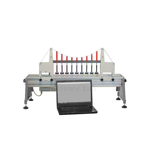
Simple Suspension Bridge
The Simple Suspension Bridge (Product Code: SLE/EG/06) is a model bridge experiment for studying how the tension in a suspension cable changes as loads are placed on the deck. Students predict the tension from theory, then compare it with the value measured by a load cell that can be logged through the Structures Platform. Additional masses let them apply either a single point load or a uniformly distributed load (UDL). The model is manufactured by Jain Scientific Equipments Pvt Ltd (ScienceLab), Ambala, as lab equipment for technical institutes and civil engineering departments.
Key Details
| Parameter | Detail |
|---|---|
| Type | Suspension bridge model for cable tension experiments |
| Measured quantity | Cable tension under applied load, via a load cell |
| Load types | Single point load and uniformly distributed load (UDL) |
| Included masses | Additional masses for the UDL and point load cases |
| Data connection | Load cell connects to the USB interface hub of the Structures Platform for computer display and data acquisition |
| Theory covered | Simplified parabola-based equation and a more realistic theory based on the model |
Typical Use
A session usually starts with the unloaded bridge, so students can see how much of the cable tension already comes from the deck's own mass. They then add a point load at different positions, and afterwards spread the masses along the deck as a UDL, recording the tension from the load cell each time. Comparing the readings with the simple parabolic cable equation and with the more realistic model-based theory shows where the simpler assumption holds well and where it drifts.
One of the most memorable results is the overwhelming influence of the deck mass compared with relatively small live loads such as vehicles crossing a real bridge. That insight helps civil engineering students understand why long-span bridges are designed as they are. With logging through the Structures Platform, the model fits neatly into a modular set of engineering lab equipment in India for structures and bridge engineering teaching.
Manufacturer
This bridge model is a product of Jain Scientific Equipments Private Limited, trading as ScienceLab from Ambala in the state of Haryana, India. Our company profile gives the wider picture of what we make.
Related Laboratory Equipment
Experiments that extend the bridge and load-path topic:
- Structures Platform — needed for computer logging of the cable tension load cell
- Suspended Beam Bridge — a cantilever-and-suspended-span bridge for comparing a different structural form
- Two Pinned Arch — an arch that, like a cable, carries load mainly in direct force; also tested with point and UDL loads
- Bending Moments In a Beam — the beam-equation background used when predicting cable tension
See all structures items in our General Products category.
Frequently Asked Questions
What does the load cell measure?
It measures the cable tension, which changes as students apply loads to the bridge.
Are masses included?
Yes, additional masses are included so students can apply a uniformly distributed load and a single point load.
Which theories are compared?
A simplified parabola-based equation and a more realistic theory based on the model itself.
Can it be used without a computer?
Our description covers display through the Structures Platform hub only. Please contact us to confirm whether a standalone readout option suits your lab.
What are the span and mass values?
These figures are not given in our current product text; we can send full technical data on request.
What warranty and certificates are available?
The warranty is confirmed in the quotation, and any need for load cell calibration paperwork should be discussed with us.
Do you take tender and export orders?
Yes. We quote for institutional tenders in India and for buyers in international markets.
Request a Quote
To price the Simple Suspension Bridge, use our contact page or collect it with related modules in the enquiry cart.
Last updated: 24 September 2026
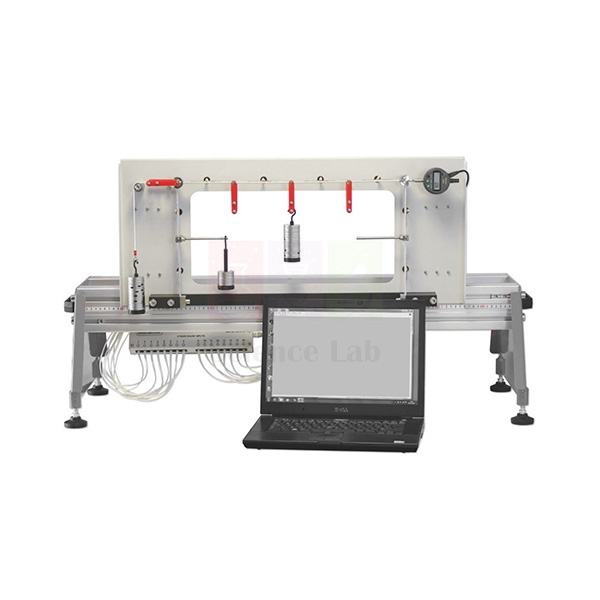
Bending Moments In A Portal Frame
Bending Moments In A Portal Frame (Product Code: SLE/EG/07) is a strain-gauged portal frame that lets students measure bending moments around a real frame and draw its bending moment diagram from test data. The frame is held between two fixing blocks and can take vertical, horizontal or combined loads, plus loads on moment arms that mimic cantilevered floors. A precision indicator records sway. The module is manufactured by Jain Scientific Equipments Pvt Ltd (ScienceLab), Ambala, whose range of vocational training and university lab equipment covers structures, fluids and materials.
Key Details
| Parameter | Detail |
|---|---|
| Type | Portal frame bending moment experiment |
| Mounting | Portal frame held between two fixing blocks |
| Load cases | Vertical, horizontal or combined loads; additional loads on moment arms on the vertical members |
| Moment arms | Simulate the effect of internal and external cantilever floors of a structure |
| Bending moment measurement | Strain gauges at key points around the portal |
| Sway measurement | Precision indicator for horizontal deflection |
| Data connection | Strain gauges connect to a strain gauge amplifier, which connects to the USB interface hub of the Structures Platform |
| Included measuring tool | Vernier caliper for measuring the cross-section |
Typical Use
Students first measure the frame section with the Vernier caliper and use textbook methods, such as moment distribution or the flexibility method, to predict bending moments at the gauge positions and the expected sway. They then apply the chosen load case and read the strains, converting each to a bending moment. Because the gauges sit at key points around the portal, the measured values can be joined up into a bending moment diagram and laid directly over the calculated one.
Running several load cases shows how the diagram changes shape: a vertical load on the beam, a horizontal load at eaves level, the two combined, and loads on the moment arms that represent floors projecting inside or outside the frame. Comparing sway with prediction completes the picture. This makes it a valuable piece of engineering educational equipment for building-frame analysis in civil and structural programmes.
Manufacturer
The module is made by Jain Scientific Equipments Private Limited, the Ambala, Haryana company behind the ScienceLab brand and a registered MSME manufacturer (Udyam UDYAM-HR-01-0003714). International consignments are shipped under Importer-Exporter Code AAECJ8618A issued by the DGFT. Read about us on the company profile page.
Related Laboratory Equipment
Modules often bought together with this portal frame:
- Structures Platform — its USB hub receives the amplified strain gauge signals for logging
- Frame Deflections And Reactions — measures base reactions and fixing moments to complement the moment diagram
- Plastic Bending of Portals — follows the elastic study with plastic hinge formation and collapse
- Bending Stress In a Beam — a single-beam strain gauge exercise that prepares students for the frame
The whole structures range is in our General Products category.
Frequently Asked Questions
How is the bending moment measured?
Strain gauges at key points around the portal measure strain, from which the bending moment at each point is calculated.
What are the moment arms for?
Loads hung on moment arms on the vertical members simulate internal and external cantilever floors, adding a realistic load case.
Is a strain gauge amplifier needed?
Yes, the strain gauges connect through a strain gauge amplifier to the Structures Platform hub. Please contact us to confirm whether the amplifier is part of your supply.
Is the Vernier caliper included?
Yes, a Vernier caliper is included for measuring the cross-section.
What load range and frame dimensions apply?
Numerical specifications are not listed in our current description; ask us for the datasheet.
Are warranty and calibration papers provided?
Warranty is stated in the quotation. Calibration documentation for the sensors can be discussed with us before ordering.
Can you supply overseas universities?
Yes, we supply institutions across India and in international markets.
Request a Quote
Request a quotation for Bending Moments In A Portal Frame through our contact page, or add it to the enquiry cart to combine it with other structures modules.
Last updated: 24 September 2026
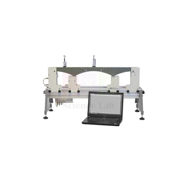
Suspended Beam Bridge
The Suspended Beam Bridge (Product Code: SLE/EG/08) models a cantilever bridge in which two outer anchor sections carry a short central span hung between their cantilever tips. Load cells in the supports and within the bridge measure both the support reactions and the internal reactions where the suspended span meets the cantilevers, so students can test textbook predictions for a statically determinate bridge that can still achieve a large central span. It is manufactured by Jain Scientific Equipments Pvt Ltd (ScienceLab), Ambala, a technical educational equipment manufacturer for civil engineering and polytechnic laboratories.
Key Details
| Parameter | Detail |
|---|---|
| Type | Cantilever and suspended-span bridge model |
| Anchor sections | Two outer anchor sections, each on two supports |
| Suspended section | Short central section carried by a short cantilever on each anchor section |
| Supports | Four, each with pointers that work with the scale on the Structures Platform |
| Reaction measurement | Load cells in the supports and in the bridge structure |
| Quantities measured | Support reactions and internal reactions between the cantilever and suspended sections |
| Loading | Loads can be applied at any position on the bridge |
| Data connection | Load cells connect to the USB interface hub of the Structures Platform |
Typical Use
Students set out the four supports using the pointers and platform scale, then place a load at a chosen point along the deck. From the load cells they read the four support reactions and the two internal reactions at the joints between the cantilevers and the suspended span. Using statics alone they predict the same values, since the hinge-like joints make the bridge statically determinate, and then compare. Moving the load step by step across the bridge lets the class build influence lines for each reaction.
The model explains why this form of bridge has been used for long spans: the suspended section lets the structure span far while remaining simple to analyse and less sensitive to support settlement. It is an engaging way to link theory with real bridge design, and suits departments buying lab equipment for technical institutes that teach bridge engineering and structural analysis.
Manufacturer
Supplied under the ScienceLab name, this bridge model is manufactured by Jain Scientific Equipments Private Limited, located in Ambala, Haryana. Further information is on our company profile.
Related Laboratory Equipment
Complementary bridge and beam experiments:
- Structures Platform — provides the positioning scale and the hub for the bridge load cells
- Simple Suspension Bridge — a cable-supported bridge to contrast with the cantilever form
- Continuous and Indeterminate Beams — shows what changes when a multi-span beam is made continuous and indeterminate
- Two Pinned Arch — a further bridge form with influence line and reaction measurements
Browse the rest of the General Products range.
Frequently Asked Questions
Is the bridge statically determinate?
Yes. Unlike some other bridge designs, it is statically determinate, yet the arrangement allows large central spans.
Which reactions can be measured?
The reactions at the supports and the internal reactions between each cantilever and the suspended section.
How many supports does it use?
Four: each of the two anchor sections sits on two supports.
Are load masses supplied?
Our current description does not detail the loading masses. Please contact us for the contents list.
Does the bridge need the Structures Platform?
The supports use the platform scale and the load cells connect to its hub, so the platform is required; it is listed separately.
What about warranty and load cell calibration documents?
Warranty terms are set in the quotation; calibration documentation is discussed per order.
Can the model be supplied for a tender?
Yes. Share the tender specification and quantity, and we will quote for delivery in India or international markets.
Request a Quote
Ask for a price on the Suspended Beam Bridge by writing through our contact page, or place it in the enquiry cart.
Last updated: 24 September 2026
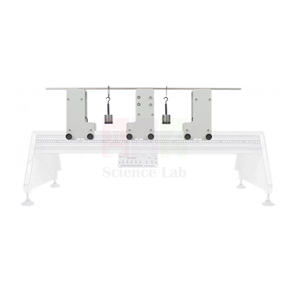
Continuous and Indeterminate Beams
Continuous and Indeterminate Beams (Product Code: SLE/EG/09) is a beam experiment set that takes students from simple, statically determinate beams to continuous and statically indeterminate beam systems. It combines a ‘rigid’ heavy beam, a light ‘flexible’ beam, a slide-mounted precision deflection indicator and two additional supports, one of which can act as a simple, clamped or sinking knife-edge support. It is manufactured by Jain Scientific Equipments Pvt Ltd (ScienceLab), Ambala, an engineering lab equipment manufacturer supplying strength of materials and structures laboratories.
Key Details
| Parameter | Detail |
|---|---|
| Type | Continuous and statically indeterminate beam experiments |
| Beams | A ‘rigid’, heavy beam and a light, ‘flexible’ beam |
| Basic supports | Two simple supports for the statically determinate experiments |
| Additional supports | Two: one allows measurement of the support fixing moment; the ‘universal support’ works as a simple support, a clamped support or a sinking knife-edge support |
| Deflection measurement | Precision indicator on a slide, easily positioned along the beam |
| Positioning | All supports and the indicator slide have pointers that work with the scale on the Structures Platform |
| Topics | Moments, principle of superposition, uniformly distributed loads; statically indeterminate beams and measurable beam deflection |
Typical Use
The first group of experiments uses the heavy ‘rigid’ beam on two simple supports. Because this beam barely deflects, students can focus on statics: taking moments, applying the principle of superposition and working with uniformly distributed loads, then confirming their reaction calculations. Once those basics are secure, they change to the light ‘flexible’ beam, where deflection becomes large enough to measure with the slide-mounted indicator.
The second group of experiments introduces the extra supports. Adding a third support makes the beam continuous and statically indeterminate; the fixing-moment support shows the moment developed at a built-in end; and the universal support, set as a sinking knife edge, lets students see how settlement of one support redistributes the forces. These exercises bring methods such as the three-moment equation or compatibility of deflections to life, making the set useful mechanics lab equipment for second- and third-year civil and mechanical courses.
Manufacturer
Jain Scientific Equipments Private Limited of Ambala, Haryana manufactures this beam set and trades as ScienceLab. You can read more about the company in our company profile.
Related Laboratory Equipment
Useful companions for a beam analysis course:
- Structures Platform — the base whose scale the supports and indicator slide are positioned against
- Deflection of Beams and Cantilevers — compares deflection across beams of different metals and sections
- Bending Moments In a Beam — measures internal bending moment directly at a cut section
- Redundant Tuss Next Generation Structures — carries the indeterminate-structure theme over to trusses
Other beam and frame modules are in our General Products category.
Frequently Asked Questions
Why are two different beams supplied?
The rigid, heavy beam isolates statics topics without noticeable deflection, while the light, flexible beam deflects enough for deflection and indeterminate-beam experiments.
What can the universal support do?
It can act as a simple support, a clamped support or a sinking knife-edge support.
How is deflection measured?
With a precision indicator mounted on a slide that can be moved to any point along the beam.
Is the Structures Platform included?
No, it is a separate item. The supports and slide are positioned using the platform scale.
Are loading weights supplied, and what are the beam sizes?
Our current description does not specify these. Please contact us for the full contents and dimensions.
How are warranty and export orders handled?
Warranty terms appear in the quotation, and we supply colleges in India and international markets.
Request a Quote
Send an enquiry for Continuous and Indeterminate Beams via our contact page, or add it to the enquiry cart to request one combined quotation.
Last updated: 24 September 2026
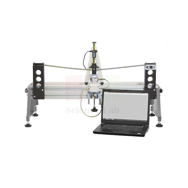
Plastic Bending Of Beams
Plastic Bending Of Beams (Product Code: SLE/EG/10) is an experiment in which a specimen beam is loaded at mid-span until it yields and forms plastic hinges, under three different end conditions: simply supported, fixed, or propped cantilever. A load cell assembly both applies and measures the force, a precision indicator tracks deformation, and one support runs on roller bearings to allow horizontal movement. It helps students see how a structural element can yield yet keep carrying load. The apparatus is made by Jain Scientific Equipments Pvt Ltd (ScienceLab), Ambala, as lab equipment for college and university structures courses.
Key Details
| Parameter | Detail |
|---|---|
| Type | Plastic bending and hinge formation experiment for beams |
| Support conditions | Simply supported, fixed or propped cantilever |
| Supports | Two; one includes roller bearings to allow horizontal translation |
| Loading | Load cell assembly applies and measures force at mid-span |
| Deformation measurement | Precision indicator |
| Concepts covered | Hinge position, failure load, yield moment, fully plastic moment and form (shape) factor |
| Prediction methods | Textbook beam equations and bending moment diagrams |
Typical Use
For each end condition, students first sketch the elastic bending moment diagram, work out the load at first yield, and predict where plastic hinges will form and what load will cause collapse. They then fit a specimen, apply load at mid-span with the load cell assembly and record force against deformation. A simply supported beam fails once a single hinge forms under the load; a propped cantilever or a fixed beam needs further hinges before it becomes a mechanism, so it carries noticeably more load beyond first yield.
Comparing the load at first yield with the collapse load leads to the ratio between yield moment and fully plastic moment, the form or shape factor, and shows how it gives an extra margin of safety. Students leave with a clear, physical sense of why ductile structures give warning before failure, which is central to modern design codes. It is well matched to departments investing in engineering educational equipment for advanced strength of materials.
Manufacturer
This apparatus is manufactured in Ambala, Haryana by Jain Scientific Equipments Private Limited, operating under the brand ScienceLab. Visit the company profile to learn about our range and approach.
Related Laboratory Equipment
Experiments and tools that fit alongside plastic beam testing:
- Plastic Bending of Portals — applies the same hinge concepts to a complete portal frame
- Bending Stress In a Beam — measures elastic bending stress, the starting point before yield
- Deflection of Beams and Cantilevers — elastic deflection for beam and cantilever cases
- Caliper Vernier (Metal) — for measuring specimen width and depth when calculating plastic moment
All structures modules are grouped in our General Products category.
Frequently Asked Questions
Which end conditions can be tested?
Simply supported, fixed and propped cantilever, allowing students to compare hinge positions and failure loads.
Where is the load applied?
At mid-span, through a load cell assembly that both applies and measures the force.
Why does one support have roller bearings?
They let that support move horizontally, so the beam is not restrained axially when that is not intended.
Are specimen beams reusable?
A beam taken into the plastic range is permanently bent. The number of specimens supplied is not stated in our current description, so please contact us about spares.
Is a Vernier caliper included?
Our description for this item does not list one; a caliper is available separately in our range.
What load capacity and specimen material apply?
Not stated in the current product text; we can provide the technical datasheet on request.
How are warranty, certificates and bulk orders handled?
Warranty is confirmed in the quotation; calibration documentation is discussed per order; and we supply multiple units to institutions in India and international markets.
Request a Quote
For a quotation on Plastic Bending Of Beams and spare specimens, contact us through the contact page or add it to your enquiry cart.
Last updated: 24 September 2026