- Physics Lab Equipment
- Chemistry Lab Equipment
- Biology Lab Equipment
- Anatomical Lab Equipment
- Learning
- Educational Lab Equipment
- Magnets
- Agriculture
- Astronomy
- Earth Science
- Geography Lab Equipment
- Safety Lab Coat
- Laboratory
- Meteorological
- Electricity & Magnetism
- Heat
- School Lab Equipment
- Lab Glassware
- Science Lab Equipment
- Tvet Lab Equipment
- Robotics Kits Supplier and Manufacturer for Schools India
- Math Lab Equipment Manufacturers and Exporters in Ambala
- STEM Kits Manufacturers and Supplier India
- Engineering Lab Equipment
- Hospital Lab Equipment
- Water, Sanitation & Hygiene Supplies
- Cold Chain, Solar & Communication Equipment
- Nutrition
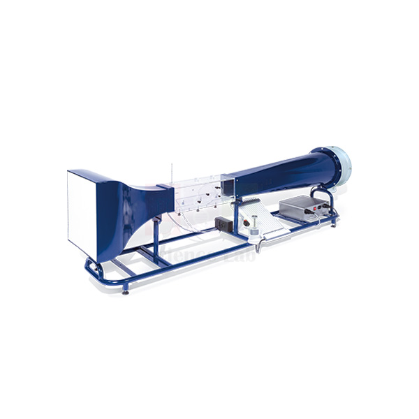
Subsonic Wind Tunnel
Subsonic Wind Tunnel (Product Code: SLE/MCE/36) is a low-speed, draw-through wind tunnel used to measure lift, drag and pressure distribution on test models in aerodynamics and fluid mechanics laboratories. Engineering colleges and polytechnics choose it for its transparent 150 x 150 mm working section, a 9.4:1 contraction ratio and computer-controlled air flow, making it a practical piece of engineering lab equipment for student groups. It is made by Jain Scientific Equipments Pvt Ltd (ScienceLab), an OEM manufacturer, at its own factory in Ambala, India.
Specifications
| Parameter | Detail |
|---|---|
| Working section | Square, nominally 150 x 150 mm (6 in nominal), length 455 mm; transparent for visibility |
| Air flow | Computer controlled; air drawn through the working section by a variable-speed fan at the discharge end |
| Inlet | Honeycomb flow straightener |
| Contraction ratio | 9.4:1 |
| Pressure measurement | 0–160 mm H2O; 16 channels 0–178 mm H2O (differential) |
| Lift force | 3.4 N at model |
| Drag force | 3.4 N at model |
| Model inclination | ±45° |
| Tube | Length 320 mm; inclination 30° |
| Cylinder | Diameter 30 mm; tapping spacing 20° |
| Throat section | Throat width 100 mm; upstream/downstream width 150 mm |
| Chord length / thickness | 61.5 mm / 9.2 mm |
| Large models | 50 mm |
| Golf ball and small sphere | 43 mm |
| Power | 220–240 V, 1 phase, 50 Hz, 10 A |
| Dimensions | 2200 x 600 x 700 mm |
| Weight | 220 kg |
| Product code | SLE/MCE/36 |
| Manufacturer | Jain Scientific Equipments Pvt Ltd (ScienceLab) — OEM |
| Country of origin | India (made in Ambala, Haryana) |
What Is the Subsonic Wind Tunnel Used For?
Students mount a model in the working section, set the fan speed from the computer and record the forces and pressures it produces. Typical exercises include plotting lift and drag against angle of attack for an aerofoil across the ±45° inclination range, reading the pressure distribution around a tapped cylinder on the 16 differential pressure channels, and comparing the drag of a golf ball with a small smooth sphere of the same 43 mm size to show how surface roughness changes the flow.
Because the fan sits at the discharge end, air enters through the honeycomb straightener and 9.4:1 contraction with little disturbance, giving a steady flow for repeatable readings. Let the speed settle before each reading, keep the lift and drag loads within 3.4 N at the model, and allow floor space for a 2200 mm long, 220 kg unit.
What to Specify When Ordering
- The set of models you need (aerofoil, cylinder, spheres, large models); ask us which are included as standard.
- Whether a computer for the air-flow control should be quoted or you will provide one.
- A 220–240 V, 50 Hz single-phase supply rated for 10 A at the installation point.
- Number of tunnels for your laboratory.
OEM Manufacturer
Jain Scientific Equipments Private Limited, which trades as ScienceLab, is the original equipment manufacturer of the Subsonic Wind Tunnel. The tunnel is built and assembled at the company's own licensed factory at 449, HSIIDC Industrial Area, Saha, Ambala, Haryana, India, and is not bought in from a trader.
Aeronautical and mechanical engineering departments, dealers and importers therefore deal directly with the maker for quotations, technical questions and spare models or replacement parts — just ask us. Read more on the company profile.
Related Aerodynamics Lab Equipment
These units build a complete aerodynamics teaching lab around the subsonic tunnel:
- Flow Visualisation Wind Tunnel — makes the streamlines around models visible with smoke.
- Flight Demonstration Wind Tunnel — shows lift, stall and stability on a free-moving model aircraft.
- Modular Air Flow Bench — a compact base unit for smaller air-flow experiment modules.
- Flow Visualisation smoke tunnel — a smoke generator and duct set for flow-pattern studies.
See all Aerodynamics Lab Equipment.
Frequently Asked Questions
What size is the working section of the Subsonic Wind Tunnel?
The Subsonic Wind Tunnel has a square working section of nominally 150 x 150 mm (6 inch nominal) and 455 mm length. It is transparent, so students can watch the model while lift, drag and pressure readings are being taken.
What can be measured on the Subsonic Wind Tunnel?
The Subsonic Wind Tunnel measures lift and drag forces of 3.4 N at the model, pressures over 0–160 mm H2O and 16 differential channels over 0–178 mm H2O, with model inclination of ±45° for angle-of-attack studies.
Which models can be tested in the Subsonic Wind Tunnel?
The Subsonic Wind Tunnel is designed for a wide range of aerodynamics and air-flow models, including a 30 mm cylinder, a 61.5 mm chord section, 50 mm large models and a 43 mm golf ball and small sphere. Ask us which models are supplied as standard.
What power and space does the Subsonic Wind Tunnel need?
The Subsonic Wind Tunnel runs on 220–240 V, single phase, 50 Hz, 10 A. It measures 2200 x 600 x 700 mm and weighs 220 kg, so plan a firm floor area with clear access around the working section.
Who manufactures the Subsonic Wind Tunnel?
The Subsonic Wind Tunnel is manufactured by Jain Scientific Equipments Pvt Ltd (ScienceLab), the OEM, at its own licensed factory in Saha, Ambala, Haryana, India. It is supplied factory-direct to institutions, dealers and importers in India and international markets.
Is a calibration certificate available for the Subsonic Wind Tunnel?
A calibration certificate for the Subsonic Wind Tunnel's force and pressure measurement is not listed as standard. If your department needs one, please discuss the requirement with us through the contact page before placing the order.
Request a Quote
Quotations for the Subsonic Wind Tunnel come straight from the manufacturer. Send your requirement via the contact page or add the tunnel to the enquiry cart.
Last updated: 24 September 2026
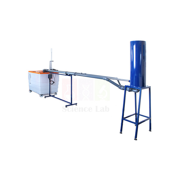
Pipe Surge and Water Hammer Apparatus
Pipe Surge and Water Hammer Apparatus (Product Code: SLE/MCE/37) is a fluid mechanics test rig used to demonstrate pipe surge and to measure water hammer pressure transients in engineering college and polytechnic laboratories. Students work with stainless steel test pipes 3 m long and 20.2 mm in bore, a fast-acting discharge valve, electronic pressure sensors and a clear acrylic surge shaft. It is made by Jain Scientific Equipments Pvt Ltd (ScienceLab), an OEM manufacturer of engineering lab equipment in India, at its own factory in Ambala.
Specifications
| Parameter | Detail |
|---|---|
| Test pipes | Stainless steel, 20.2 mm inside diameter |
| Test pipe length | 3 m |
| Water hammer pipe | Second test pipe with a fast-acting valve at the discharge |
| Pressure measurement | Tappings with electronic pressure sensors next to the fast-acting valve and half way along the test pipe |
| Surge shaft | Clear acrylic, 40 mm inside diameter, 800 mm high |
| Head tank | PVC, 45 litre capacity |
| Overall dimensions | 3500 x 800 x 1600 mm |
| Weight | 120 kg |
| Product code | SLE/MCE/37 |
| Manufacturer | Jain Scientific Equipments Pvt Ltd (ScienceLab) — OEM |
| Country of origin | India (made in Ambala, Haryana) |
What Is the Water Hammer Apparatus Used For?
When a valve at the end of a pipeline shuts quickly, the moving column of water is brought to rest and its momentum becomes a pressure wave that runs back up the pipe and reflects to and fro. On this rig students trigger that event with the fast-acting valve on the second test pipe, and the two electronic sensors capture the high-speed pressure transients as the wave travels backwards and forwards along the pipe.
Since one sensor sits beside the valve and the other half way along the pipe, the time delay between their signals gives the wave speed — the speed of sound in water, reduced by the elasticity of the metal pipe wall. The acrylic surge shaft makes the slower rise and fall of water level after a flow change visible, which links the experiment to surge tanks on hydropower and pumping mains. As lab equipment for technical institutes teaching hydraulics, it is best run with the head tank kept full and air cleared from the pipes so that repeated runs compare fairly.
OEM Manufacturer
Jain Scientific Equipments Private Limited, which trades as ScienceLab, is the OEM (original equipment manufacturer) of this Pipe Surge and Water Hammer Apparatus. The rig is built at the company's own licensed factory at 449, HSIIDC Industrial Area, Saha, Ambala, Haryana, not sourced from a trader. The company is incorporated under CIN U29309HR2020PTC087597, and the factory premises hold Factory Licence AMB-ONLINE-CHD-J-414.
Engineering colleges, universities, dealers and importers in India and international markets deal directly with the manufacturer, so questions about replacement valves, sensors or acrylic parts reach the people who build the rig — just ask us. More background is on the ScienceLab company profile.
Related Fluid Mechanics Equipment
These items from the same hydraulics range support pressure-transient, pipe-flow and pressure-measurement practicals:
- Water Hammer Apparatus — a separate water hammer set-up for comparing wave behaviour in a different pipe layout.
- Friction Loss In Pipe — covers steady-flow head loss, the companion topic to unsteady pipe flow.
- Fluid Friction Measurements — a larger pipe network trainer for losses in pipes, bends and fittings.
- Calibration of a Pressure Gauge — teaches how pressure instruments are checked before measurements are trusted.
See the complete Fluid Mechanics range for more hydraulics trainers and demonstration units.
Frequently Asked Questions
What does the Pipe Surge and Water Hammer Apparatus measure?
The Pipe Surge and Water Hammer Apparatus measures the high-speed pressure transients created when its fast-acting valve closes, using electronic pressure sensors beside the valve and half way along the 3 m test pipe. It also shows surge behaviour as a changing water level in a clear acrylic surge shaft.
How is the speed of sound in water found with this apparatus?
With the Pipe Surge and Water Hammer Apparatus, wave speed is worked out from the time delay between the two pressure sensors and their known spacing along the test pipe. The value obtained is lower than in open water, because the elastic metal pipe wall attenuates the wave.
What size are the test pipes and the surge shaft?
The test pipes of the Pipe Surge and Water Hammer Apparatus are stainless steel, 20.2 mm inside diameter and 3 m long. The surge shaft is clear acrylic with a 40 mm inside diameter and 800 mm height, and water is held in a 45 litre PVC head tank.
How much floor space does the apparatus need?
The Pipe Surge and Water Hammer Apparatus measures 3500 x 800 x 1600 mm overall and weighs 120 kg. Plan a long, level floor area with room along one side, so that students can operate the valve and watch the surge shaft and sensor readings.
How are the pressure sensor readings displayed?
The Pipe Surge and Water Hammer Apparatus picks up transients with electronic pressure sensors, but the display or data-recording arrangement offered with it should be confirmed at quotation. Please ask through the contact page which readout is supplied for your order.
Who manufactures the Pipe Surge and Water Hammer Apparatus?
The Pipe Surge and Water Hammer Apparatus is manufactured by Jain Scientific Equipments Pvt Ltd (ScienceLab), the OEM, at its own factory in Saha, Ambala, Haryana, India. It is supplied factory-direct to colleges, institutions, dealers and importers.
Is a calibration certificate available for the sensors?
Calibration certificate availability for the sensors on the Pipe Surge and Water Hammer Apparatus should be discussed with us before you order. State your requirement in the enquiry so that it can be answered in the quotation.
Request a Quote
To request a quotation for the Pipe Surge and Water Hammer Apparatus (SLE/MCE/37), send your quantity and delivery location through the contact page or add it to the enquiry cart. Quotations come directly from the manufacturer in Ambala for single laboratory sets and larger institutional orders.
Last updated: 24 September 2026
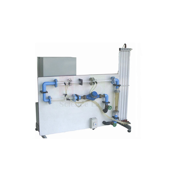
Orifice and Venturi meter demonstrator
Orifice and Venturi meter demonstrator (Product Code: SLE/MCE/38) is a flow measurement teaching unit used to compare a Venturi meter, a variable area meter and an orifice plate in hydraulics laboratories. The three meters sit in series on one circuit, read against an 8-tube manometer of 0 to 500 mm water column, and the unit stands on a hydraulics bench for its water supply. It is made by Jain Scientific Equipments Pvt Ltd (ScienceLab), an OEM manufacturer, at its own factory in Ambala, India.
Specifications
| Parameter | Detail |
|---|---|
| Flow meters | Venturi meter, variable area meter and orifice plate, installed in series |
| Variable area meter range | 2 to 30 l/min |
| Manometer | 8 tubes, 0 to 500 mm water column, pressurised with a hand pump |
| Venturi upstream pipe diameter | 32 mm |
| Venturi throat diameter | 20 mm |
| Venturi taper angles | 21° and 14° |
| Orifice plate | Upstream pipe diameter 35 mm, orifice diameter 19 mm (an orifice plate diameter of 25 mm is also listed — confirm when ordering) |
| Flow control | Flow control valve to vary the flow rate through the circuit |
| Head loss measurement | Pressure tappings across each flow meter |
| Mounting and water supply | Support framework standing on the working top of a hydraulics bench, which supplies water and is used for volumetric calibration |
| Product code | SLE/MCE/38 |
| Manufacturer | Jain Scientific Equipments Pvt Ltd (ScienceLab) — OEM |
| Country of origin | India (made in Ambala, Haryana) |
What Is the Orifice and Venturi Meter Demonstrator Used For?
Differential-pressure flow meters are everywhere in water supply and process plants, and this demonstrator lets students see how three common types behave when exactly the same flow passes through each. They set a flow with the control valve, read the manometer levels at the tappings, and then collect a timed volume in the bench tank to find the true flow rate for comparison.
From those readings a class can work out the coefficient of discharge of the Venturi and the orifice plate, check the variable area meter scale, and compare the permanent head loss each meter causes — the Venturi recovers most of its pressure drop, while the orifice plate does not. Repeating the test at several valve settings across the 2 to 30 l/min range builds calibration curves, a staple exercise for engineering educational equipment in India's polytechnics and colleges.
What to Specify When Ordering
- Whether your laboratory already has a hydraulics bench to supply water and measure volume, since the demonstrator stands on one.
- Confirmation of the orifice plate dimensions required for your syllabus.
- Number of units, based on how many student groups run the experiment at once.
OEM Manufacturer
This Orifice and Venturi meter demonstrator is manufactured by Jain Scientific Equipments Private Limited, the company behind the ScienceLab brand. As the OEM (original equipment manufacturer), ScienceLab builds and assembles the meter circuit, manometer board and framework at its own licensed factory at Saha, Ambala, Haryana, India.
Buying from the maker means one point of contact for quotations, repeat units for additional lab benches and replacement manometer tubes or fittings — ask us about the parts you need. Colleges, training institutes, dealers and importers are supplied factory-direct; the ScienceLab company profile has more about the company.
Related Fluid Mechanics Equipment
These products extend flow measurement practicals or support the calibration step:
- Flow Meter Demonstration Unit — a similar three-meter comparison unit with a 15 mm Venturi throat and a smaller meter range.
- Bernoulli's Theorem — studies the pressure and velocity changes along a converging-diverging section.
- Cavitation In Venturi — shows what happens when throat pressure falls too low.
- Bench Stopwatch — times the volumetric tank fill when calibrating each meter.
Browse the full Fluid Mechanics category for more hydraulics lab apparatus.
Frequently Asked Questions
Which flow meters does the Orifice and Venturi meter demonstrator compare?
The Orifice and Venturi meter demonstrator compares a Venturi meter, a variable area meter and an orifice plate installed in series. Because the same flow passes through all three, students can compare their readings and head losses directly at each valve setting.
Does the demonstrator need a hydraulics bench?
Yes. The Orifice and Venturi meter demonstrator stands on the working top of a hydraulics bench, which supplies the water and provides the volumetric tank used to calibrate each meter. If your laboratory has no bench, mention this in your enquiry.
What is the manometer range?
The Orifice and Venturi meter demonstrator uses an 8-tube manometer with a range of 0 to 500 mm water column. A hand pump pressurises the manometer so that the water levels can be brought within the readable part of the scale.
What are the Venturi meter dimensions?
The Venturi meter on the Orifice and Venturi meter demonstrator has a 32 mm upstream pipe diameter and a 20 mm throat diameter, with taper angles of 21° and 14° listed for its converging and diverging sections.
What flow range can be measured?
The variable area meter on the Orifice and Venturi meter demonstrator reads from 2 to 30 l/min. The flow control valve lets students set several flow rates within this range to build calibration curves for the Venturi meter and the orifice plate.
Who manufactures the Orifice and Venturi meter demonstrator?
The Orifice and Venturi meter demonstrator is manufactured by Jain Scientific Equipments Pvt Ltd (ScienceLab), the OEM, at its own factory in Ambala, Haryana, India, and quotations come straight from the manufacturer.
Is a calibration certificate supplied?
Calibration certificate availability for the Orifice and Venturi meter demonstrator should be discussed with us before ordering. Please state the requirement through the contact page so it is covered in your quotation.
Request a Quote
For a quotation on the Orifice and Venturi meter demonstrator (SLE/MCE/38), use the contact page or place it in the enquiry cart with your quantity and delivery location. Prices and terms are quoted direct by the manufacturer for buyers in India and international markets.
Last updated: 24 September 2026
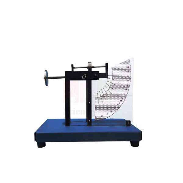
Hydrostatic Pressure Apparatus
Hydrostatic Pressure Apparatus (Product Code: SLE/MCE/39) is a fluid statics bench unit used to determine the resultant force and centre of pressure on a submerged plane surface in engineering and physics laboratories. Students hang masses from a swinging arm carrying a quadrant over a 5.5 litre acrylic tank, testing the face vertical or inclined and partly or fully under water. It is made by Jain Scientific Equipments Pvt Ltd (ScienceLab), an OEM manufacturer, at its own factory in Ambala, India.
Specifications
| Parameter | Detail |
|---|---|
| Tank | Clear acrylic, 5.5 litre capacity, with graduated scale showing the water level |
| Levelling | Adjustable screwed feet and a circular spirit level on the tank base |
| Balance arm | Swinging arm with a tray and an adjustable counterbalance, mounted on top of the tank |
| Area of the section | 0.007 m² |
| Total depth of submerged quadrant | 160 mm |
| Height of support point on the quadrant | 100 mm |
| Distance from suspended masses to support point | 285 mm |
| Dimensions | 600 x 400 x 400 mm |
| Weight | 30 kg |
| Product code | SLE/MCE/39 |
| Manufacturer | Jain Scientific Equipments Pvt Ltd (ScienceLab) — OEM |
| Country of origin | India (made in Ambala, Haryana) |
Experiments listed for the apparatus:
- Centre of pressure and resultant force with the surface at 90°, partially submerged.
- Centre of pressure and resultant force with the surface at 90°, totally submerged.
- Centre of pressure, resultant force and equivalent force with the surface at angles other than 90°, partially and totally submerged.
- Balance of moments about the support point.
What Is the Hydrostatic Pressure Apparatus Used For?
Dams, lock gates, tank walls and sluices all have to resist water pressure that grows with depth, so the resultant force acts below the centroid of the wetted face. This apparatus turns that idea into a measurement: with the tank levelled and the empty arm balanced by the counterbalance, students add water, restore balance by loading masses on the tray, and read the water level from the graduated scale.
Taking moments about the support point, with the masses acting 285 mm from it, gives the hydrostatic force and the depth of the centre of pressure, which are compared with theory for partial and full submersion. Tilting the face to angles other than 90° extends the exercise to inclined surfaces. It is compact bench-top engineering lab equipment in India's college syllabi and fits easily on a standard laboratory table.
OEM Manufacturer
Jain Scientific Equipments Private Limited (trading as ScienceLab) is the OEM, or original equipment manufacturer, of the Hydrostatic Pressure Apparatus. The acrylic tank, quadrant and balance arm assembly are made at the company's own licensed factory at Saha, Ambala, Haryana, so the product is supplied by the maker itself rather than by an intermediary.
Schools of engineering, polytechnics, dealers and importers can order single units or class sets straight from the factory, and later requests for spare quadrants or counterbalance parts go back to the same team — ask us. Company details are on the ScienceLab profile page.
Related Fluid Mechanics Equipment
Useful additions for a fluid statics practical session:
- Hangers with Slotted Weights — masses for balancing the hydrostatic moment on the arm.
- Center of Pressure — another centre-of-pressure set for comparing designs or equipping more groups.
- Fluid Properties and Hydrostatics Bench — a mobile bench covering density, viscosity, buoyancy and pressure measurement.
- Pressure Measurement Bench — extends the topic to manometers and pressure gauges.
More hydrostatics and hydraulics apparatus is listed in the Fluid Mechanics category.
Frequently Asked Questions
What experiments can be done with the Hydrostatic Pressure Apparatus?
The Hydrostatic Pressure Apparatus is used to find the resultant force and centre of pressure on a submerged surface at 90° and at other angles, partially and totally submerged, together with the equivalent force and a balance of moments about the support point.
What is the tank capacity?
The acrylic tank of the Hydrostatic Pressure Apparatus holds 5.5 litres of water. A graduated scale on the tank shows the water level reached, which students need for calculating the depth of the centre of pressure in each test.
What are the quadrant dimensions?
On the Hydrostatic Pressure Apparatus, the submerged quadrant has a total depth of 160 mm and a section area of 0.007 m². The support point sits 100 mm above the quadrant, and the suspended masses act 285 mm from the support point.
How is the apparatus levelled?
The Hydrostatic Pressure Apparatus is levelled with the adjustable screwed feet under its acrylic tank. Correct alignment is shown by a circular spirit level on the tank base, and the arm is then zeroed with the adjustable counterbalance before water is added.
Are the masses included with the apparatus?
The masses used on the tray of the Hydrostatic Pressure Apparatus should be confirmed at quotation, because the scope of supply is not listed here. Ask through the contact page, or add a set of slotted weights to your enquiry.
Who manufactures the Hydrostatic Pressure Apparatus?
The Hydrostatic Pressure Apparatus is manufactured by Jain Scientific Equipments Pvt Ltd (ScienceLab), which is the OEM and builds it at its own factory in Ambala, Haryana, India for colleges, institutions, dealers and importers.
Request a Quote
Ask for a quotation on the Hydrostatic Pressure Apparatus (SLE/MCE/39) through the contact page, or add it to the enquiry cart and state the number of units needed. Every quotation is prepared directly by the manufacturer, including for export orders.
Last updated: 24 September 2026
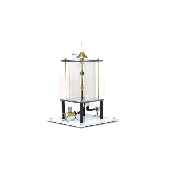
Impact of a Jet Apparatus
Impact of a Jet Apparatus (Product Code: SLE/MCE/40) is a hydraulics experiment unit used to measure the force a water jet exerts on flat and curved surfaces, so students can verify the momentum equation in fluid mechanics laboratories. An 8 mm jet inside a clear acrylic cylinder strikes interchangeable 40 mm targets — flat, 120° curved and 180° hemispherical — balanced by calibrated masses. It is made by Jain Scientific Equipments Pvt Ltd (ScienceLab), an OEM and engineering lab equipment manufacturer, at its own factory in Ambala, India.
Specifications
| Parameter | Detail |
|---|---|
| Construction | Cylindrical tank with transparent sides; discharge nozzle inside a clear acrylic cylinder |
| Jet diameter | 8 mm |
| Impact surfaces | 90° flat surface, 120° curved surface and 180° hemispherical surface |
| Impact surface diameter | 40 mm |
| Force measurement | Weight-loaded scale; the vertical jet force is balanced with calibrated weights |
| Masses supplied | Set of 5, 10, 50 and 100 g masses |
| Counterbalance | Compression spring offsets the dead weight of the moving parts |
| Water supply and drainage | Nozzle connected to a hydraulics bench; drain holes in the tank base |
| Dimensions | 800 x 800 x 800 mm |
| Weight | 90 kg |
| Product code | SLE/MCE/40 |
| Manufacturer | Jain Scientific Equipments Pvt Ltd (ScienceLab) — OEM |
| Country of origin | India (made in Ambala, Haryana) |
What Is the Impact of a Jet Apparatus Used For?
Turbine blades, spray nozzles and fire hoses all depend on the force produced when a moving stream of water changes direction. In this experiment the jet rises from the nozzle, hits the target and is deflected; the force it produces is found by adding calibrated weights until the lever returns to its level mark, while the flow rate is measured on the hydraulics bench.
Comparing the three targets shows why shape matters: the flat plate turns the jet through 90°, the 120° curved surface turns it further, and the hemispherical cup almost reverses it, giving the largest force for the same flow. Students plot measured force against the rate of momentum flow and compare the slope with theory. For a technical educational equipment manufacturer's customers — polytechnics and engineering colleges — it is also the natural lead-in to Pelton wheel tests.
OEM Manufacturer
ScienceLab is the brand name of Jain Scientific Equipments Private Limited, the original equipment manufacturer (OEM) of this Impact of a Jet Apparatus. It is fabricated and assembled at the company's own licensed factory at Saha, Ambala, Haryana, India, with the acrylic cylinder, lever system and target set built to go together.
Because you are dealing with the manufacturer, extra impact surfaces, replacement nozzles or additional mass sets can be requested from the same source that built the unit — ask us. Institutions, dealers and importers in India and international markets are served factory-direct; learn more on the ScienceLab company profile.
Related Fluid Mechanics Equipment
Products that follow on from jet impact studies or help with flow measurement:
- Pelton Turbine Test Rig — puts the same jet-deflection principle to work driving an impulse turbine.
- Pelton Wheel (Turbine) — another impulse turbine unit for performance tests.
- Orifice and Venturi meter demonstrator — a second accessory that runs on the same hydraulics bench.
- Bench Stopwatch — for timing the volume collected when measuring flow rate.
Explore the whole Fluid Mechanics category for more bench-top hydraulics experiments.
Frequently Asked Questions
What does the Impact of a Jet Apparatus measure?
The Impact of a Jet Apparatus measures the vertical force of an 8 mm water jet striking a target, by balancing it with calibrated weights on a weight-loaded scale. Students compare this force with the rate of momentum change calculated from the flow rate.
Which impact surfaces come with the apparatus?
The Impact of a Jet Apparatus has three impact surfaces, each 40 mm in diameter: a 90° flat surface, a 120° curved surface and a 180° hemispherical surface. Swapping them shows how deflection angle changes the jet force.
Are weights supplied with the Impact of a Jet Apparatus?
Yes. A set of 5, 10, 50 and 100 g masses is supplied with the Impact of a Jet Apparatus, and these calibrated weights are used on the weight-loaded scale to balance the force of the jet.
What water supply does the apparatus need?
The Impact of a Jet Apparatus has its nozzle connected to a hydraulics bench, which provides the water and is normally used to measure flow rate. Water leaves through holes in the tank base. If you do not have a bench, mention it when you enquire.
What is the compression spring for?
In the Impact of a Jet Apparatus, a compression spring counterbalances the dead weight of the moving parts. That way the calibrated weights added during a test balance only the force of the water jet, not the weight of the mechanism itself.
Who manufactures the Impact of a Jet Apparatus?
The Impact of a Jet Apparatus is manufactured by Jain Scientific Equipments Pvt Ltd (ScienceLab), the OEM, at its own factory in Ambala, Haryana, India, and it is supplied factory-direct to engineering institutions, dealers and importers.
Request a Quote
Send an enquiry for the Impact of a Jet Apparatus (SLE/MCE/40) through the contact page, or add it to the enquiry cart along with any other hydraulics units you need. The quotation comes directly from the manufacturer in Ambala.
Last updated: 24 September 2026
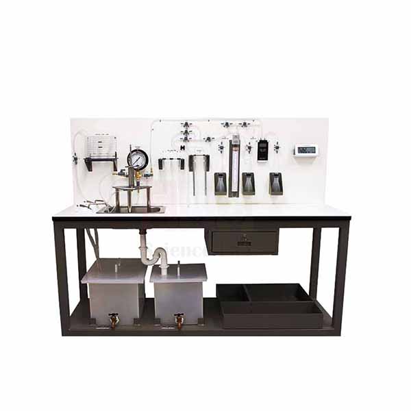
Fluid Properties and Hydrostatics Bench
Fluid Properties and Hydrostatics Bench (Product Code: SLE/MCE/41) is a mobile laboratory trolley used to teach density, viscosity, capillarity, buoyancy and pressure measurement in fluid mechanics courses. It carries its own sealed water circuit with a 0.22 kW submersible pump and a cabinet of modules, from falling-sphere viscometer tubes to an Archimedes set, so it works without a mains water connection. It is made by Jain Scientific Equipments Pvt Ltd (ScienceLab), an OEM manufacturer, at its own factory in Ambala, India.
Specifications
| Parameter | Detail |
|---|---|
| Construction | Laboratory trolley with demonstration panel, working area and cabinet; pipe section with pressure measuring devices and integrated measuring containers |
| Water circuit | Sealed circuit with pump and supply tank, independent of mains water |
| Submersible pump | 0.22 kW; flow rate 95 L/min; head 12.5 m |
| U-tube manometer | 0 to 500 mm water column |
| Mercury (Hg) U-tube manometer | 270–0–270 mbar |
| Aneroid barometer | 973 to 1047 mbar |
| Thermometer | -10 to 50 °C |
| Pycnometer | 50 ml |
| Hydrometer jars | Two, 450 x 50 mm |
| Falling sphere viscometer tubes | Two, 300 x 40 mm, with marks at 0, 25, 175, 200 and 220 |
| Stainless steel balls | 3.175 mm, 2.381 mm and 1.588 mm diameters |
| Capillary tubes module | Tubes of 5, 4, 3, 2.2, 1.7 and 1.2 mm |
| Other capillarity module | Parallel plates capillary module |
| Archimedes module | Displacement vessel, bucket and cylinder, used with a variable scale lever balance up to 310 g |
| Centre of pressure device | Included in the cabinet; also allows the pressure on a weir to be determined |
| Dimensions | 1000 x 800 x 1400 mm |
| Weight | 120 kg |
| Product code | SLE/MCE/41 |
| Manufacturer | Jain Scientific Equipments Pvt Ltd (ScienceLab) — OEM |
| Country of origin | India (made in Ambala, Haryana) |
What Is the Fluid Properties Bench Used For?
Before students move on to flowing water, they need a feel for the properties that govern it, and this bench gathers those first-semester practicals on one trolley. Density is found with the 50 ml pycnometer and the hydrometer jars, buoyancy with the Archimedes module and lever balance, and hydrostatic force with the centre of pressure device. The manometers and aneroid barometer compare gauge and atmospheric pressure readings.
For viscosity, steel balls of three sizes are dropped through the falling-sphere tubes and timed between the marks, giving data for Stokes' law. The capillary tubes module, from 5 mm down to 1.2 mm bore, turns into a classic capillary tube experiment for colleges in India, showing how rise height grows as the bore gets smaller, while the parallel plates show the same effect between flat surfaces. Being on a trolley, the bench can be wheeled between rooms and shared by several groups.
OEM Manufacturer
Jain Scientific Equipments Private Limited, known by its brand ScienceLab, is the OEM (original equipment manufacturer) of the Fluid Properties and Hydrostatics Bench. The trolley, pipe section and module cabinet are assembled at the company's own licensed factory at Saha, Ambala, Haryana. ScienceLab is a registered MSME enterprise whose major activity is manufacturing (Udyam UDYAM-HR-01-0003714), and export consignments are handled under Importer-Exporter Code AAECJ8618A (DGFT).
Colleges, universities, dealers and importers in India and international markets order direct from the factory, and replacement glassware or modules for the bench can be requested from the same team — ask us. Read more on the ScienceLab company profile.
Related Fluid Mechanics Equipment
Pair the bench with these units for a fuller fluid properties and statics course:
- Viscosity And Particle Drag — goes further into drag on particles settling through a fluid.
- Hydrostatic Pressure Apparatus — a dedicated bench-top centre of pressure rig for extra student groups.
- Pressure Measurement Bench — more practice with manometers and pressure gauges.
- Kinematic Viscometer Bath — a stirred, temperature-controlled bath for viscometer tube measurements.
The Fluid Mechanics category lists the complete hydraulics range.
Frequently Asked Questions
What experiments can be done on the Fluid Properties and Hydrostatics Bench?
The Fluid Properties and Hydrostatics Bench covers density with a pycnometer and hydrometer jars, falling-sphere viscosity, capillarity in tubes and between plates, Archimedes' principle, centre of pressure, pressure on a weir, and gauge and barometric pressure measurement.
Does the bench need a mains water connection?
No. The Fluid Properties and Hydrostatics Bench has a sealed water circuit with its own supply tank and a 0.22 kW submersible pump rated at 95 L/min and 12.5 m head, so experiments run independently of a mains water connection.
How is viscosity measured on the bench?
Viscosity is measured on the Fluid Properties and Hydrostatics Bench with two falling-sphere tubes, 300 x 40 mm, and stainless steel balls of 3.175, 2.381 and 1.588 mm. Students time each ball between the marks and apply Stokes' law.
Which pressure instruments are included?
The Fluid Properties and Hydrostatics Bench includes a U-tube manometer of 0 to 500 mm water column, a mercury U-tube manometer reading 270–0–270 mbar and an aneroid barometer with a 973 to 1047 mbar range, plus a -10 to 50 °C thermometer.
How large is the Fluid Properties and Hydrostatics Bench?
The Fluid Properties and Hydrostatics Bench measures 1000 x 800 x 1400 mm and weighs 120 kg. It is built on a laboratory trolley, so it can be moved between laboratories and shared by several student groups.
Who manufactures the Fluid Properties and Hydrostatics Bench?
The Fluid Properties and Hydrostatics Bench is manufactured by Jain Scientific Equipments Pvt Ltd (ScienceLab), the OEM, at its own factory in Ambala, Haryana, India. Quotations and spare-part requests are handled directly by the manufacturer.
Request a Quote
Request pricing for the Fluid Properties and Hydrostatics Bench (SLE/MCE/41) via the contact page, or add it to the enquiry cart with your delivery location. You receive the quotation directly from the manufacturer.
Last updated: 24 September 2026
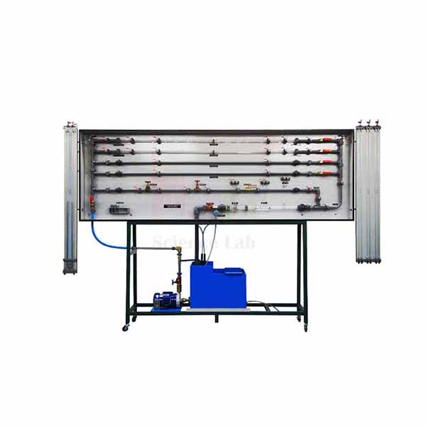
Fluid Friction Measurements
Fluid Friction Measurements (Product Code: SLE/MCE/42) is a pipe-flow trainer used to measure friction losses in straight pipes, fittings and flow meters in engineering and polytechnic hydraulics laboratories. It combines four smooth-bore pipes from 4.5 mm to 17.2 mm inside diameter, an artificially roughened pipe, a range of bends and elbows and 38 tapping points on one closed water circuit. It is made by Jain Scientific Equipments Pvt Ltd (ScienceLab), an OEM manufacturer, at its own factory in Ambala, India.
Specifications
| Parameter | Detail |
|---|---|
| Smooth-bore pipes | 4 pipes of different diameters, 4.5 mm to 17.2 mm inside diameter |
| Rough pipe | Artificially roughened pipe |
| Fittings | 90° bends (large and small radii), 90° elbow, 90° mitre, 45° elbow, 45° Y, 90° T |
| Other test sections | Inline strainer, Perspex Venturi, Perspex orifice meter, Perspex pipe section with Pitot tube and static tapping |
| Tapping points | 38, designed as annular chambers |
| Pressure | Bourdon tube pressure gauge, -1 to 1.5 bar |
| Differential pressure | 1 differential pressure sensor, 0 to ±350 mbar; 8 tube manometers, 0 to 1000 mm water column |
| Flow rate | Rotameter, 400 to 4000 L/h; volumetric measuring tank for timed measurements |
| Water circuit | Closed circuit with tank and submersible pump |
| Manometer panel | Movable, for space saving and easy access |
| Power supply | 230 V, 50 Hz, 1 phase |
| Dimensions | 800 x 800 x 1200 mm |
| Weight | 120 kg |
| Product code | SLE/MCE/42 |
| Manufacturer | Jain Scientific Equipments Pvt Ltd (ScienceLab) — OEM |
| Country of origin | India (made in Ambala, Haryana) |
What Is the Fluid Friction Apparatus Used For?
Every pipeline designer has to estimate how much head is lost to wall friction and fittings, and this trainer lets students measure those losses rather than just read them from charts. Water from the submersible pump is routed through one test section at a time; the pressure drop is read across the annular-chamber tappings and plotted against the flow rate, taken from the rotameter or from a timed fill of the volumetric tank.
Comparing the four smooth pipes shows how friction factor depends on Reynolds number, the roughened pipe brings in relative roughness, and the bends, elbows, mitre, Y and T give loss coefficients for fittings. The Perspex Venturi, orifice meter and Pitot tube add flow measurement to the same session. Use the stopwatch method at low flows, where it is more accurate than reading the rotameter. The trainer suits TVET lab equipment programmes in India as well as university hydraulics courses.
What to Specify When Ordering
- Electrical supply at the installation point: the trainer runs on 230 V, 50 Hz, single phase.
- Floor space for the 800 x 800 x 1200 mm unit and access around the movable manometer panel.
- Whether you need a stopwatch for the volumetric measurements.
- Number of trainers and the delivery location.
OEM Manufacturer
The Fluid Friction Measurements trainer is made by Jain Scientific Equipments Private Limited, which trades under the ScienceLab name and acts as the OEM (original equipment manufacturer). Pipework, fittings, manometer panel and frame are put together at the company's own licensed factory at Saha, Ambala, Haryana, rather than bought in from a reseller.
Quotations, repeat orders and requests for replacement pipe sections or manometer tubes all go to the manufacturer itself — ask us. Engineering colleges, training institutes, dealers and importers are supplied factory-direct; see the ScienceLab company profile for more.
Related Fluid Mechanics Equipment
Other items for pipe-flow and loss experiments:
- Friction Loss In Pipe — a simpler single-pipe unit for laminar and turbulent friction studies.
- Pipe Flow And Nozzle Kit — pipe loss and velocity-profile tests with air instead of water.
- Pipe Surge and Water Hammer Apparatus — moves on from steady to unsteady pipe flow.
- Bench Stopwatch — for timing the volumetric tank during flow measurement.
Find more hydraulics trainers in the Fluid Mechanics category.
Frequently Asked Questions
Which losses can be measured with the Fluid Friction Measurements trainer?
The Fluid Friction Measurements trainer measures friction losses in four smooth pipes and a roughened pipe, and local losses in 90° and 45° bends and elbows, a mitre, a Y, a T, an inline strainer, a Venturi and an orifice meter.
How is flow rate measured?
Flow rate on the Fluid Friction Measurements trainer is read from a rotameter covering 400 to 4000 L/h, or found by timing a fill of the volumetric measuring tank with a stopwatch, which gives accurate results even at low flow rates.
What pressure instruments does the trainer use?
The Fluid Friction Measurements trainer uses eight tube manometers of 0 to 1000 mm water column, a differential pressure sensor of 0 to ±350 mbar and a Bourdon tube pressure gauge reading -1 to 1.5 bar, connected to 38 tapping points.
Does it need a separate water supply?
No. The Fluid Friction Measurements trainer has a closed water circuit with its own tank and submersible pump, so it only needs filling with water and a 230 V, 50 Hz, single-phase electrical supply to operate.
Who manufactures the Fluid Friction Measurements trainer?
The Fluid Friction Measurements trainer is manufactured by Jain Scientific Equipments Pvt Ltd (ScienceLab), the OEM, at its own factory in Ambala, Haryana, India, and it is supplied direct to colleges, institutes, dealers and importers.
Can a calibration certificate be provided for the instruments?
Calibration certificate availability for the gauges and sensor on the Fluid Friction Measurements trainer should be discussed with us before ordering. Please raise it through the contact page so it is addressed in the quotation.
Request a Quote
Get a quotation for Fluid Friction Measurements (SLE/MCE/42) by writing to us on the contact page or adding it to the enquiry cart. Quotations are issued directly by the manufacturer for buyers in India and international markets.
Last updated: 24 September 2026
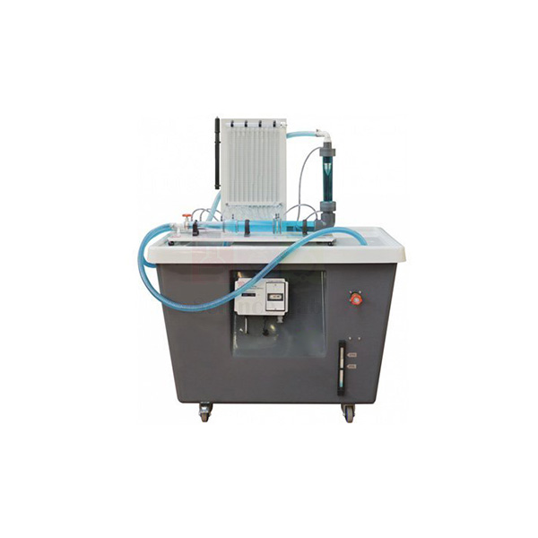
Flow Meter Demonstration Unit
Flow Meter Demonstration Unit (Product Code: SLE/MCE/43) is a hydraulics bench accessory used to compare and calibrate a Venturi meter, a variable area meter and an orifice plate in fluid mechanics laboratories. Its eight-tube manometer also traces the pressure curve along the Venturi, which has a 15 mm throat, while the variable area meter reads 2 to 20 l/min. It is made by Jain Scientific Equipments Pvt Ltd (ScienceLab), an OEM manufacturer of lab equipment for technical institutes, at its own factory in Ambala, India.
Specifications
| Parameter | Detail |
|---|---|
| Flow meters | Venturi meter, variable area meter and orifice plate, with a flow-control valve |
| Manometer board | 8 tubes, 0 to 400 mm range, pressurised with a hand pump |
| Venturi throat diameter | 15 mm |
| Upstream pipe diameter | 31.75 mm |
| Upstream taper | 21° inclusive |
| Downstream taper | 14° inclusive |
| Orifice plate diameter | 20 mm |
| Variable area meter | 2 to 20 l/min |
| Head loss measurement | Pressure tappings across each meter |
| Water supply and calibration | Placed on a hydraulics bench, which supplies the water and provides the volumetric measuring tank |
| Dimensions (as listed) | 800 x 800 x 1200 mm |
| Weight (as listed) | 120 kg |
| Product code | SLE/MCE/43 |
| Manufacturer | Jain Scientific Equipments Pvt Ltd (ScienceLab) — OEM |
| Country of origin | India (made in Ambala, Haryana) |
What Is the Flow Meter Demonstration Unit Used For?
The unit answers a practical question students will meet in industry: which meter should be fitted, and how far can its reading be trusted? With the circuit standing on the hydraulics bench, the class sets a flow on the control valve, reads the three meters, then collects water in the bench's volumetric tank against a stopwatch to get the true flow for calibrating each one.
Because the manometer tubes are spread along the Venturi, the same readings show the pressure falling into the 15 mm throat and recovering through the 14° diffuser — a direct check of Bernoulli's equation and of the continuity principle. The tappings across each device then reveal how much head each meter permanently costs the system. Pressurising the manometer with the hand pump keeps all eight levels on the scale at higher flows.
OEM Manufacturer
ScienceLab is the trading name of Jain Scientific Equipments Private Limited, and the company is the OEM (original equipment manufacturer) of this Flow Meter Demonstration Unit. The meter circuit, manometer board and support framework are produced at its own licensed factory at Saha, Ambala, Haryana, India, and the unit ships from there directly to the buyer.
Dealing with the maker helps when a laboratory later needs an additional unit, a new manometer tube or a replacement fitting — ask us and the request goes straight to production. Universities, polytechnics, dealers and importers in India and international markets are supplied factory-direct. More on the company: ScienceLab company profile.
Related Fluid Mechanics Equipment
Other bench accessories and aids for flow measurement practicals:
- Orifice and Venturi meter demonstrator — a comparable unit with a 20 mm Venturi throat and a wider 2 to 30 l/min meter.
- Bernoulli's Theorem — a dedicated unit for the pressure-velocity relationship.
- Impact of a Jet Apparatus — another experiment that runs from the same hydraulics bench.
- Stopwatch, Digital — times the volumetric tank for calibration.
The Fluid Mechanics category has the rest of the hydraulics range.
Frequently Asked Questions
Which flow meters does the Flow Meter Demonstration Unit include?
The Flow Meter Demonstration Unit includes a Venturi meter, a variable area meter and an orifice plate, with a flow-control valve and pressure tappings across each meter, so students can compare readings and head losses directly.
What manometer comes with the unit?
The Flow Meter Demonstration Unit is supplied with a manometer board of eight tubes and a 0 to 400 mm range. A hand pump pressurises the manometer so the levels stay readable, and several tubes trace the pressure curve along the Venturi.
What are the Venturi and orifice dimensions?
On the Flow Meter Demonstration Unit, the Venturi has a 31.75 mm upstream pipe diameter, a 15 mm throat, a 21° inclusive upstream taper and a 14° inclusive downstream taper. The orifice plate diameter is 20 mm.
Is a hydraulics bench required?
Yes. The Flow Meter Demonstration Unit is placed on a hydraulics bench, which supplies the water and provides the volumetric measuring tank used to calibrate each flow meter. Tell us in your enquiry if your laboratory does not have a bench.
What flow range does the variable area meter cover?
The variable area meter on the Flow Meter Demonstration Unit reads from 2 to 20 l/min. Within that range students set several flows with the control valve and plot calibration curves for the Venturi meter and the orifice plate.
Who manufactures the Flow Meter Demonstration Unit?
The Flow Meter Demonstration Unit is manufactured by Jain Scientific Equipments Pvt Ltd (ScienceLab), the OEM, at its own factory in Ambala, Haryana, India, and quotations come straight from the manufacturer.
Request a Quote
For prices and delivery terms on the Flow Meter Demonstration Unit (SLE/MCE/43), contact us through the contact page or add it to the enquiry cart. The manufacturer quotes directly for single units and institutional quantities.
Last updated: 24 September 2026